


3-2
C
HAPTER
3: F
EATURES
AND
S
PECIFICATIONS
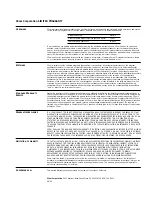
LEDs
There are nine LEDs on the front panel of the DPE module:
■
RUN and LOAD
— green
■
TEST
— yellow
■
STATUS
— four green LEDs
■
PACKET FORWARD
— green
■
POWER/FAULT
— green or yellow
for LED patterns and their meanings.
LEDs on the Chassis
There are two LEDs on the front of the chassis. The green POWER LED indicates
whether the system is off or on. The STATUS LED is exactly the same as the
POWER/FAULT LED on the DPE module. Refer to “LED Patterns”
more information.
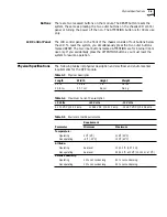
Connectors
Table 3-2 describes the module connectors.
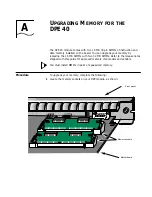
CONSOLE
connector
Flash memory
drives (A, B)
STATUS
LEDs
(1,2,3,4)
ATTENTION
LED
RESET
LED
Backplane
connectors to
NETBuilder II
J1
J3
J2
J5
J4
J6
®
DPE
PACKET
FORWARD
POWER/
FAULT
RUN
LOAD
TEST
RESET
ATTENTION
4
3
2
1
STATUS
CONSOLE
A
B
RUN
LOAD
TEST
LEDs
POWER/
FAULT
LED
PACKET
FORWARD
LED
Table 3-2
DPE Module Connectors
Location
Connectors
Features
Device Type
Purpose
Backplane
connectors
J1, J2, J3, J4,
J5, and J6
48-pin
-
Connects module to the core bus.
Front LED/connector
panel
CONSOLE
connector
9-pin male
D-subminiature (RS-232)
DTE
Connects module to a modem or terminal. See
“Connecting a PC, Terminal, or Modem”
on
for more information.