background image

5

4

Check the LEDs

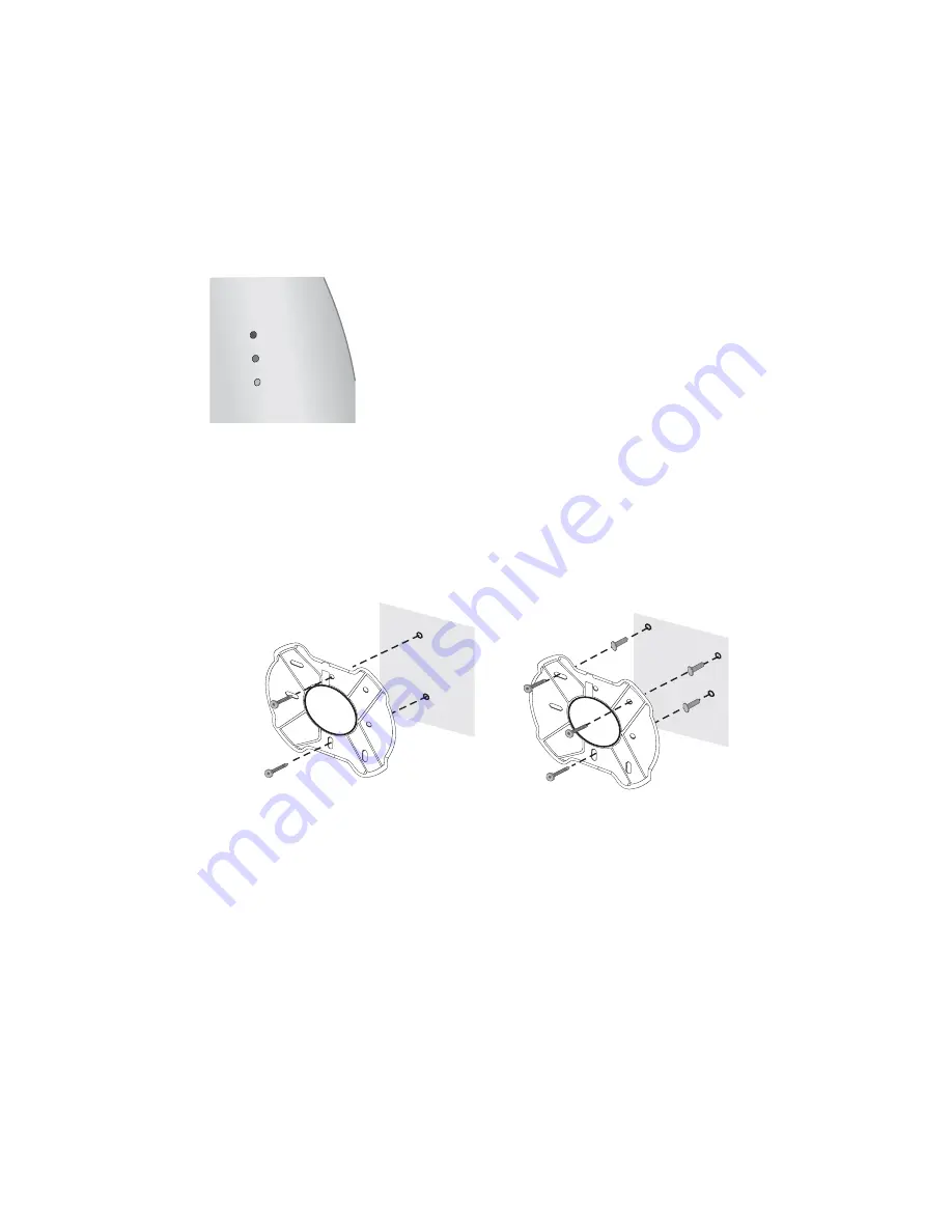
When power is connected, the access point LEDs light up. The illustration and the following table describe the 
LEDs and their functions.

5

Wall Mount Installation

1

Install the mounting plate as shown in the following illustration, on either a stud (or other 
hard wall surface), or onto drywall.

Allow for a clearance of at least 25 cm (10 inches) between the ceiling and the top of the 
mounting plate.

Orient the bracket with the letter “B” at the top of the bracket.

For installation on a wall stud, install the top screw into the stud, as shown at left in the 
illustration, and then vertically align the mounting plate before installing the 
bottom screw. 

For installation on to drywall, mark three screw holes using the mounting plate as a 
template for vertical alignment, as shown at right in the illustration above. 

Use a 5-mm (3/16-in.) drill bit if using the plastic anchors provided.

For drywall mounts, you can route the cable through the center opening for a seamless 
appearance using one of the methods illustrated below. Alternatively, you can simply 
attach the Ethernet cable to the top of the unit, allowing it to trail along the wall.

Name

Description

Radio

LED blinks red to indicate radio activity. Faster blinking 
indicates more activity.

Ethernet

LED lights yellow when 10 Mbps Ethernet link is 
established. LED lights green when 100 Mbps Ethernet 
link is established. LED blinks to indicate activity on the 
Ethernet. Faster blinking indicates more activity.

Power

LED lights green when operational code is running. LED 
lights yellow when a power-on fault occurs.

RADIO

ETHERNET

POWER

If installing into drywall, use 3 plastic

anchors and 3 screws

.

If installing into a stud or other
secure vertical surface, use 2 screws.

A

B

A

B

Содержание 7250

Страница 1: ...scalability It extends networks and boosts productivity for centrally managed enterprises requiring scalable security solutions NOTE This product must be installed by a professional technician installer CAUTION Do not connect a telephone cable into the Ethernet port doing so can cause serious damage to the access point R ad io E th er ne t P ow er Access Point 7250 Front Console port Ethernet port...

Страница 2: ...power rated 48 V DC 350 mA maximum Such equipment must be safety certified according to UL CSA IEC or other applicable national or international safety requirements for the country of use All references to the power supply refer to equipment that meets these requirements Because the power supply plug is the only means of disconnecting the access point from power make sure the power outlet is acces...

Страница 3: ...optional 3Com Integrated Power over Ethernet power supply In this case you need to supply a second Ethernet cable to connect to the wired LAN Connect the access point directly to your own Power over Ethernet hub or switch which must also comply with the IEEE 802 3af standard Using the Included AC Adapter The power supply included with the Access Point 7250 is an AC adapter Follow these steps to co...

Страница 4: ...thernet port on the access point 2 Connect the other end of the Ethernet cable to the port labeled To Access Point on the power supply 3 Connect the power cord to the power supply and plug the cord into a power outlet 4 To link the access point to your Ethernet network plug one end of another Ethernet cable into the port labeled To Hub Switch on the power supply and plug the other end into a LAN p...

Страница 5: ...al alignment as shown at right in the illustration above Use a 5 mm 3 16 in drill bit if using the plastic anchors provided For drywall mounts you can route the cable through the center opening for a seamless appearance using one of the methods illustrated below Alternatively you can simply attach the Ethernet cable to the top of the unit allowing it to trail along the wall Name Description Radio ...

Страница 6: ...it snaps into place as shown below 6 Flat Surface Installation 1 Find a clean and dry surface that is elevated enough to provide good reception and coverage for the network Do not place the access point on a metal surface 2 Make sure to choose a location where the access point will not be disturbed 3 Connect the Ethernet cable into the Ethernet port 4 Connect the power cable to the power port on t...

Страница 7: ...Com 3CDaemon Server Tool This tool can act in four different capacities As a TFTP Server necessary for firmware upgrades and backup and restore functions Use this option if you do not have a TFTP server set up As a SysLog Server which is necessary to view SysLog messages As an optional TFTP Client As an optional FTP Server 3Com Network Supervisor The 3Com Network Supervisor 3NS graphically discove...

Страница 8: ...red The default login is admin and there is no password After installing and launching the device manager select the device to be configured from network tree and click Configure to launch the configuration Web interface Refer to the Access Point 7250 User Guide included on the installation CD for detailed information and instructions on locating and configuring the access point The first time you...

Отзывы: