Device
Placement
on
the
Layout
Model
3Com
®
AirProtect
Planner
User
Guide
86
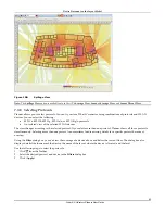
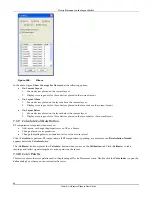
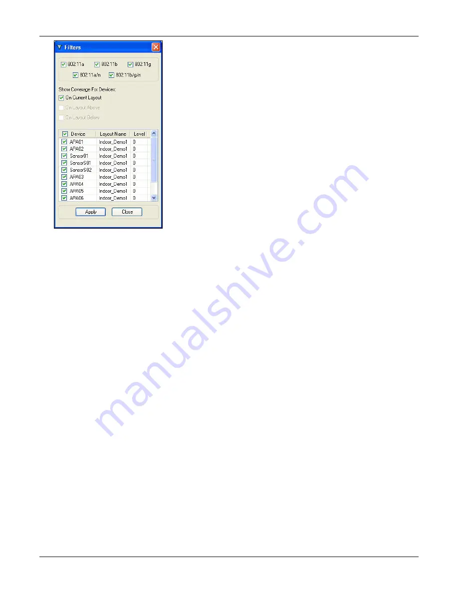
Figure 109.
Filters
In
the
above
figure,
Show
Coverage
For
Devices
has
the
following
options:
•
On
Current
Layout
1.
Shows
devices
placed
on
the
current
layout
2.
Displays
coverage
only
for
those
devices
placed
on
the
current
layout
•
On
Layout
Above
1.
Shows
devices
placed
on
the
layout
above
the
current
layout
2.
Displays
coverage
only
for
those
devices
placed
on
the
layout
above
the
current
layout
•
On
Layout
Below
1.
Shows
devices
placed
on
the
layout
below
the
current
layout
2.
Displays
coverage
only
for
those
devices
placed
on
the
layout
below
the
current
layout
7.3.9
Calculate/Calibrate
Button
RF
computation
is
required
whenever
you:
•
Add,
move,
or
change
the
properties
of
an
AP
or
a
Sensor
•
Change
a
layout
or
its
properties
•
Change
the
spillage
factor,
attenuation
factor,
or
the
accuracy
level
Click
<
Calculate
>
to
perform
RF
computations.
If
RF
computation
is
pending,
a
comment
in
red
‘
Recalculation
Needed
’
appears
below
the
Calculate
button.
The
<
Calibrate
>
button
replaces
the
<
Calculate
>
button
when
you
are
on
the
Calibration
tab.
Click
<
Calibrate
>
to
take
readings
and
collect
signal
strengths
at
various
points
on
the
layout.
7.3.10
Color
Palette
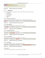
This
section
shows
the
color
palette
used
in
the
planning
of
Device
Placement
views.
Double
‐
click
the
Color
Index
to
open
the
Color
dialog
box
where
you
can
customize
the
colors.


