7
2
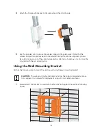
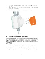
Position the bracket in the intended location and mark the position of the four mounting
screw holes.
3
Drill four holes in the wall that match the screws and wall plugs included in the bracket kit,
then secure the bracket to the wall.
4
Use the included nuts to tightly secure the wireless bridge to the bracket.
4
Connecting External Antennas
The bridge's primary antenna is it's built-in internal antenna. For some applications when deploying an
WL-575 unit for a bridge link or access point operation, you may need to mount external antennas and
connect them to the bridge. Typically, a bridge link requires a 5.0 GHz antenna, and access point
operation a 2.4 GHz antenna. WL-575 units acting as managed APs also require an external antenna for
2.4 GHz operation.
Perform these steps:
1
Mount the external antenna to the same supporting structure as the bridge, within 3 m
(10 ft) distance, using the bracket supplied in the antenna package.
2
Connect the antenna to the bridge’s N-type connector using the RF coaxial cable provided in
the antenna package.
3
Apply weatherproofing tape to the antenna connectors to help prevent water entering the
connectors.

