Configuring Traffic Prioritization on the Switch
71
■
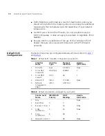
Otherwise, if there are no other classifiers except the 802.1p tag, then
the packet will pass through the Switch with the original 802.1p
priority tag.
■
Otherwise, if the received packet does not have an 802.1p tag, then a
default 802.1p tag (which is usually 0) is assigned to it.
Traffic Queues
It is the multiple traffic queues within the Switch hardware that allow
packet prioritization to occur. Higher priority traffic can pass through the
Switch without being delayed by lower priority traffic. As each packet
arrives in the Switch, it passes through any ingress processing (which
includes classification, marking/remarking or dropping), and is then
sorted into the appropriate queue. The Switch then forwards packets
from each queue. It is worth noting that each egress port has its own set
of queues, so that if one port is congested it does not interfere with the
queue operation of other ports.
The Switch uses the Weighted Round Robin (WRR) queuing mechanism.
This method services all the traffic queues, giving priority to the higher
priority queues. Under most circumstances, this method gives high
priority precedence over low-priority, but in the event that high-priority
traffic exceeds the link capacity, lower priority traffic is not blocked.
Traffic queues cannot be enabled on a per-port basis on the Switch 4400.
Configuring Traffic
Prioritization on the
Switch
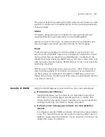
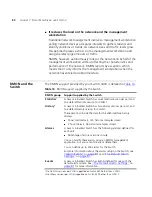
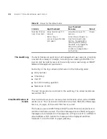
Your Switch allows you to discard and prioritize applications as well as
devices to obtain Quality of Service (QoS) for your network. Configuring
traffic prioritization on the Switch is referred to as QoS configuration, and
you must follow the following sequence of steps:
1 Traffic Classification
— first identify the types of traffic requiring special
treatment. This is called creating a Classifier. Your Switch is capable of
identifying traffic from many of the various attributes of an incoming
packet, as shown in
Table 5
on
page 64
. Traffic classification can be
determined by various attributes across the seven layers of the OSI model.
The Switch then groups classified traffic in order to schedule them with
the appropriate service level. Your Switch has five default Classifiers as
shown in
Table 7
on
page 74
.
2 Service Levels
— you can create and modify service levels to determine
the priority that will be applied to each classified traffic type. For example,
the Switch can discard the traffic or Re-mark it from the DiffServ Code
Point (DSCP) to an 802.1D priority to ensure the packet is prioritized
Содержание 3C17205-US - Corp SUPERSTACK 3 SWITCH 4400...
Страница 8: ...GLOSSARY INDEX...
Страница 14: ...14...
Страница 26: ...26 CHAPTER 1 SWITCH FEATURES OVERVIEW...
Страница 44: ...44 CHAPTER 3 USING MULTICAST FILTERING...
Страница 55: ...How STP Works 55 Figure 13 STP configurations...
Страница 58: ...58 CHAPTER 4 USING RESILIENCE FEATURES...
Страница 84: ...84 CHAPTER 7 STATUS MONITORING AND STATISTICS...
Страница 92: ...92 CHAPTER 8 SETTING UP VIRTUAL LANS...
Страница 98: ...98 CHAPTER 9 USING WEBCACHE SUPPORT...
Страница 120: ...120 CHAPTER 12 POWER MANAGEMENT AND CONTROL...
Страница 122: ...122...
Страница 126: ...126 APPENDIX A CONFIGURATION RULES...
Страница 134: ...134 APPENDIX B NETWORK CONFIGURATION EXAMPLES...
Страница 150: ...150 GLOSSARY...

