background image

Rack-mounting

25

The air is as free from dust as possible.

The unit is installed in a clean, air conditioned environment.

No more than eight Switch units are placed on top of one another, if 
the units are free-standing.

The Switch is situated away from sources of conductive (electrical) 
dust, for example laser printers.

The AC supply used by the Switch is separate to that used by units 
that generate high levels of AC noise, for example air conditioning 
units and laser printers.

Rack-mounting

The Switch 4400 is 1U high and will fit in most standard 19-inch racks. 

CAUTION:

Disconnect all cables from the Switch before continuing. 

Remove all self adhesive pads from the underside of the Switch if they 
have been fitted.

To rack-mount your Switch:

1

Place the Switch the right way up on a hard flat surface, with the front 
facing towards you.

2

Locate a mounting bracket over the mounting holes on one side of the 
Switch, as shown in Figure 6.

DUA1720-3AAA06.book  Page 25  Thursday, June 5, 2003  4:01 PM

Содержание 3C17205 - SuperStack 3 Switch 4400 PWR

Страница 1: ...6 Published June 2003 SuperStack 3 Switch 4400 Series Getting Started Guide Switch 4400 3C17203 Switch 4400 3C17204 Switch 4400 PWR 3C17205 Switch 4400 SE 3C17206 Switch 4400 FX 3C17210 DUA1720 3AAA06 book Page 1 Thursday June 5 2003 4 01 PM ...

Страница 2: ... documentation contained in or delivered to you in conjunction with this User Guide Unless otherwise indicated 3Com registered trademarks are registered in the United States and may or may not be registered in other countries 3Com the 3Com logo and SuperStack are registered trademarks of 3Com Corporation Intel and Pentium are registered trademarks of Intel Corporation Microsoft MS DOS Windows and ...

Страница 3: ... 14 Summary of Hardware Features 14 Switch 4400 Front View Detail 15 10BASE T 100BASE TX Ports 16 100BASE FX Ports 16 LEDs 17 Switch 4400 Rear View Detail 19 Power Socket 19 Redundant Power System Socket 19 Console Port 19 Expansion Module Slots 19 Default Settings 20 2 INSTALLING THE SWITCH Package Contents 24 Choosing a Suitable Site 24 Rack mounting 25 Placing Units On Top of Each Other 27 Stac...

Страница 4: ...ng to a Front Panel Port 39 Connecting to the Console Port 42 Viewing Automatically Configured IP Information 46 Using 3Com Network Supervisor 46 Connecting to the Console Port 46 Methods of Managing a Switch 49 Command Line Interface Management 49 Web Interface Management 50 SNMP Management 50 Setting Up Command Line Interface Management 50 CLI Management via the Console Port 50 CLI Management ov...

Страница 5: ...1 PC AT Serial Cable 71 Modem Cable 72 RJ 45 Pin Assignments 72 C TECHNICAL SPECIFICATIONS Switch 4400 24 port and Switch 4400 SE 75 Switch 4400 PWR 24 port 77 Switch 4400 48 port 78 Switch 4400 FX 79 D TECHNICAL SUPPORT Online Technical Services 81 World Wide Web Site 81 3Com Knowledgebase Web Services 82 3Com FTP Site 82 Support from Your Network Supplier 82 Support from 3Com 83 Internet Support...

Страница 6: ...INDEX REGULATORY NOTICES DUA1720 3AAA06 book Page 6 Thursday June 5 2003 4 01 PM ...

Страница 7: ...or installing and setting up network equipment consequently it assumes a basic working knowledge of LANs Local Area Networks Before You Start This section contains information about the documents and CD ROM that accompany your Switch 4400 Release Notes The Release Notes provide important information about the current software release including new features modifications and known problems You shou...

Страница 8: ...ation that alerts you to potential loss of data or potential damage to an application system or device Warning Information that alerts you to potential personal injury Table 2 Text Conventions Convention Description Screen displays This typeface represents information as it appears on the screen Syntax The word syntax means that you must evaluate the syntax provided and then supply the appropriate...

Страница 9: ...ormation about the web interface and command line interface that enable you to manage the Switch It is supplied in HTML format on the CD ROM that accompanies the Switch Release Notes The words enter and type When you see the word enter in this guide you must type something and then press Return or Enter Do not press Return or Enter when an instruction simply says type Keyboard key names If you mus...

Страница 10: ...lect the Documentation section from the contents page If the online documentation is to be accessed from a local drive or server you will need to access the CD ROM contents via the root directory and copy the files from the CD ROM to a suitable directory The HTML Reference Guide is stored in the Docs reference directory on the CD ROM The documentation is accessed using the contents htm file The PD...

Страница 11: ...ond to comments and questions about 3Com product documentation at this e mail address Questions related to technical support or sales should be directed in the first instance to your network supplier Product Registration You can now register your SuperStack 3 Switch on the 3Com web site to receive up to date information on your product http www 3com com register DUA1720 3AAA06 book Page 11 Thursda...

Страница 12: ...12 ABOUT THIS GUIDE DUA1720 3AAA06 book Page 12 Thursday June 5 2003 4 01 PM ...

Страница 13: ...t the Switch 4400 and how it can be used in your network It covers summaries of hardware and software features and also the following topics About the Switch 4400 Switch 4400 Front View Detail Switch 4400 Rear View Detail Default Settings DUA1720 3AAA06 book Page 13 Thursday June 5 2003 4 01 PM ...

Страница 14: ... links Summary of Hardware Features Table 3 summarizes the hardware features that are supported by the Switch 4400 Table 3 Hardware features Feature Switch 4400 Addresses Up to 8000 supported Up to 64 permanent entries Auto negotiation Supported on all ports Auto MDI MDI X not 3C17210 Forwarding Modes Store and Forward Duplex Modes Half and full duplex on all front panel ports Flow Control In full...

Страница 15: ... Detail 15 Switch 4400 Front View Detail Figure 1 Switch 4400 FX front view Figure 2 Switch 4400 24 port Switch 4400 SE front view Figure 3 Switch 4400 PWR front view DUA1720 3AAA06 book Page 15 Thursday June 5 2003 4 01 PM ...

Страница 16: ...hese ports automatically provide the appropriate connection Alternatively you can manually set these ports to 10BASE T half duplex 10BASE T full duplex 100BASE TX half duplex or 100BASE TX full duplex The maximum segment length is 100 m 328 ft over Category 5 twisted pair cable The 4400 PWR will supply up to 15 4W of power through any of the 24 front panel ports in conformance to the 802 3af speci...

Страница 17: ...llow If a port fails the Switch passes its Power On Self Test and continues to operate normally Off The Switch is not receiving power or there is a fault with the Power Supply Unit Port LEDs Packet Green Full duplex packets are being transmitted received on the port Yellow Half duplex packets are being transmitted received on the port Off No packets are being transmitted received on the port Statu...

Страница 18: ...continues to operate normally even if one or more modules are disabled Unit LEDs 1 8 Green When the Switch forms a stack with other Switch 4400 units the LED indicates the position of the unit in the stack and that a link is present When the Switch is stand alone and not part of a stack LED 1 is on Green sequential When a software upgrade is in progress the Unit LEDs of the unit that is being upgr...

Страница 19: ... management The console port uses a standard null modem cable and is set to auto baud 8 data bits no parity and 1 stop bit Expansion Module Slots You can use these slots to install Expansion Modules These allow the Switch to support various forms of connection and add extra functionality to your Switch For example you can install a Cascade module to enable the Switch to be stacked with other Switc...

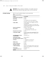
Страница 20: ...de 100 HD if required Power over Ethernet Enabled 3C17205 only Flow Control Enabled in half duplex mode Auto negotiated in full duplex mode Broadcast Storm Control Enabled Virtual LANs VLANs All ports belong to the untagged Default VLAN VLAN 1 with IEEE Std 802 1Q 1998 learning operational Link Aggregation Control Protocol LACP Disabled per port IP Multicast Filtering Filtering enabled Rapid Spann...

Страница 21: ...4400 SE Enhanced Software Upgrade 3C17207 If you initialize a Switch unit by selecting System Control Initialize in the Web interface or by entering system control initialize in the Command Line Interface the following settings are retained to allow you to connect to and manage the Switch IP Address Subnet Mask Default Router DUA1720 3AAA06 book Page 21 Thursday June 5 2003 4 01 PM ...

Страница 22: ...22 CHAPTER 1 INTRODUCING THE SUPERSTACK 3 SWITCH 4400 DUA1720 3AAA06 book Page 22 Thursday June 5 2003 4 01 PM ...

Страница 23: ... read the safety information provided in Appendix A of this guide AVERTISSEMENT Consignes de sécurité Avant d installer ou d enlever tout composant du Switch 4400 ou d entamer une procédure de maintenance lisez les informations relatives à la sécurité qui se trouvent dans l Appendice A de ce guide VORSICHT Sicherheitsinformationen Bevor Sie Komponenten aus dem Switch 4400 entfernen oder dem Switch...

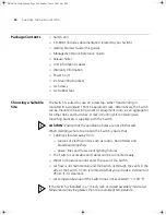
Страница 24: ...upplied with the Switch CAUTION Ensure that the ventilation holes are not obstructed When deciding where to position the Switch ensure that Cabling is located away from sources of electrical noise such as radios transmitters and broadband amplifiers power lines and fluorescent lighting fixtures The Switch is accessible and cables can be connected easily Water or moisture cannot enter the case of t...

Страница 25: ...te high levels of AC noise for example air conditioning units and laser printers Rack mounting The Switch 4400 is 1U high and will fit in most standard 19 inch racks CAUTION Disconnect all cables from the Switch before continuing Remove all self adhesive pads from the underside of the Switch if they have been fitted To rack mount your Switch 1 Place the Switch the right way up on a hard flat surfa...

Страница 26: ...Switch into the 19 inch rack and secure with suitable screws not provided Ensure that ventilation holes are not obstructed 6 Connect network cabling 7 Finally place a unit information label on the unit in an easily accessible position The unit information label shows the following The 3Com product name of the Switch The 3Com 3C number of the Switch The unique MAC address Ethernet address of the Sw...

Страница 27: ...y combination of 24 port and 48 port units is allowed in a single stack as long as the total number of front panel ports does not exceed the limit of 192 ports The following combinations are allowed 4 x 48 port Switches 3 x 48 port Switches and 2 x 24 port Switches 2 x 48 port Switches and 4 x 24 port Switches 1 x 48 port Switch and 6 x 24 port Switches 8 x 24 port Switches The SuperStack 3 Switch...

Страница 28: ...400 units For information on ordering the Cascade Kits contact your supplier For illustrations and information on how to install the Cascade Kits refer to the user documentation that accompanies these Kits SuperStack 3 Cascade Module 3C17224 SuperStack 3 Cascade Module 3C17224 DOWN UP Switch 1 Switch 2 Module 2 Module 2 SuperStack 3 Cascade Module 3C17224 Switch 1 SuperStack 3 Cascade Module 3C172...

Страница 29: ...cade Modules into Expansion Module Slot 2 on the Switches It is not possible to stack a Switch 4400 Switch 4400 SE Switch 4400 PWR or Switch 4400 FX unit with SuperStack II or other SuperStack 3 products using the Cascade Stacking Kit 3C17227 or Cascade Extender Kit 3C17228 3Com strongly recommends that you upgrade all Switch 4400 units 24 port and 48 port in a stack to the latest software agent 3...

Страница 30: ...ED Table 6 Power Self Test LED colors If there is evidence of a problem see Solving Problems Indicated by LEDs on page 56 Connecting a Redundant Power System You can connect a SuperStack 3 Advanced Redundant Power System 3C16071B to the Switch This unit which is also known as an RPS is designed to maintain the power to your Switch if a power supply failure occurs For normal redundancy the Switch 4...

Страница 31: ... LAN Building to Building Bridge 3CRWE91096B Voice Over IP Telephones 3Com 11 Mbps Wireless LAN Access Point 8000 3CRWE80096B 3Com 11 Mbps Wireless LAN Access Point 8200 3CRWE820096A 3Com 11 Mbps Wireless LAN Access Point 8500 3CRWE850096A 3Com Wireless LAN Building to Building Bridge 3CRWE91096B The following 3Com NBX phones are also supported using the 3Com NBX VoIP Phone Module 3CNJVOIPMOD NBX ...

Страница 32: ...to a port with a straight through MDI or a cross over cable MDIX The Auto MDIX feature only operates when auto negotiation is enabled If auto negotiation is disabled all the Switch ports are configured as MDIX cross over If you want to make a connection to another MDIX port you need a cross over cable Many ports on workstations and servers are configured as MDI straight through If you want to make...

Страница 33: ...with the transmit and receive fibers in the same cable Unlike many fiber optic systems only one MT RJ cable is needed to connect two MT RJ ports together To connect a front panel port to another 100BASE FX MT RJ multi mode port or to a patch panel a single MT RJ multi mode pinless jumper cable is required Since standard MT RJ cables are cross over cables no Auto MDIX sensing is required The maximu...

Страница 34: ...34 CHAPTER 2 INSTALLING THE SWITCH DUA1720 3AAA06 book Page 34 Thursday June 5 2003 4 01 PM ...

Страница 35: ...ou to improve the efficiency of the Switch and therefore the overall performance of your network This chapter explains the initial set up of the Switch and the different methods of accessing the management software to manage a Switch It covers the following topics Setting Up Overview Manually Configuring IP Information Viewing Automatically Configured IP Information Methods of Managing a Switch Se...

Страница 36: ...r Up the Switch IP Information is automatically configured See page 37 Do you want to manually configure the IP information Connect to a front panel port and use the Web Interface or Command Line Interface See page 39 How do you want to manage your Switch See page 49 SNMP See page 53 Command Line Interface Connect via the console port See page 50 Web Interface Connect over the network via Telnet S...

Страница 37: ...sses Static IP addresses are necessary to ensure that the Switch is always allocated the same IP information For most installations 3Com recommends that you configure the Switch IP information manually This makes management simpler and more reliable as it is not dependent on a DHCP or BootP server and eliminates the risk of the IP address changing If you wish to manually enter IP information for y...

Страница 38: ...mentation Guide on the CD ROM that accompanies your Switch or on the 3Com Web site You should use the automatic IP configuration method if your network uses DHCP or BootP to allocate IP information or flexibility is needed If the Switch is re deployed onto a different subnet it will automatically reconfigure itself with an appropriate IP address instead of you having to manually reconfigure the Sw...

Страница 39: ...to a Front Panel Port To set up your Switch manually you can make a connection to a front panel port You must do this whilst the Switch is offline that is before you connect the Switch to a network The procedure described in this section assumes the unit has been powered up in standalone mode and has the default IP address of 169 254 100 100 Pre requisites A workstation running Windows 95 98 2000 ...

Страница 40: ... Information You need to change the IP address and subnet mask of the workstation that you have connected to the Switch Make a note of the existing settings so you can return to them later Change the workstation to the following settings IP address 169 254 100 99 Subnet mask 255 255 0 0 Setting Up the Switch with IP Information You are now ready to manually set up the Switch with IP information Yo...

Страница 41: ...ial set up of your Switch is now complete and the Switch is ready for you to set up your chosen management method See Methods of Managing a Switch on page 49 Using Command Line Interface via Telnet 1 To start a Telnet session to the unit click Start in Microsoft Windows 95 98 2000 NT XP a Click Run b In the dialogue box that appears type the default IP address of the unit that is Telnet 169 254 10...

Страница 42: ...g the gettingStarted command you will then be prompted to enter system information change passwords and then given the option to carry out advanced configuration The initial set up of your Switch is now complete and the Switch is ready for you to set up your chosen management method See Methods of Managing a Switch on page 49 Connecting to the Console Port To set up your Switch manually you can al...

Страница 43: ...in Appendix B on page 71 You need to have the following so that you can manually set up the Switch with IP information IP address subnet mask default gateway Connecting the Workstation to the Switch 1 Connect the workstation to the console port using a standard null modem cable as shown in Figure 12 Figure 12 Connecting a workstation to the Switch via the console port To connect the cable a Attach...

Страница 44: ...itch with IP Information You are now ready to manually set up the Switch with IP information using the command line interface 1 The command line interface login sequence begins as soon as the Switch detects a connection to its console port If the login prompt does not begin immediately press Return a few times until it starts 2 At the login and password prompts enter admin as your user name and pr...

Страница 45: ... and gateway IP address for the Switch The screen displays a summary of the information entered If using the gettingStarted command you will then be prompted to enter system information change passwords and then given the option to carry out advanced configuration The initial set up of your Switch is now complete and the Switch is ready for you to set up your chosen management method See Methods o...

Страница 46: ...Supervisor and run the Auto discovery wizard 3Com Network Supervisor will auto discover the new Switch and display the IP information that has been automatically allocated to the Switch Most DHCP and BootP servers allow static IP addresses to be configured so that you know what IP address the Switch will be given Refer to the documentation that accompanies your DHCP or BootP server If your network...

Страница 47: ...rkstation to the Switch via the console port To connect the cable a Attach the female connector on the cable to the male connector on the console port of the Switch b Tighten the retaining screws on the cable to prevent it from being loosened c Connect the other end of the cable to one of the serial ports also known as a COM port on your workstation 2 Open your terminal emulation software and conf...

Страница 48: ...9 254 x y where x is in the range 1 to 254 and y is in the range 0 to 255 2 The command line interface login sequence begins as soon as the Switch detects a connection to its console port If the login prompt does not begin immediately press Return a few times until it starts 3 At the login and password prompts enter admin as your user name and press Return at the password prompt If you have logged...

Страница 49: ...itial set up of your Switch you can decide how you wish to manage the Switch You can use one of the following methods Command line interface management Web interface management SNMP management Command Line Interface Management Each Switch has a command line interface CLI that allows you to manage the Switch from a workstation either locally via a console port connection see Figure 16 or remotely o...

Страница 50: ...ovided on the CD ROM that accompanies your Switch Figure 19 SNMP management over the network Refer to Setting Up SNMP Management on page 53 Setting Up Command Line Interface Management This section describes how you can set up command line interface management using a local console port connection or over the network CLI Management via the Console Port To manage a Switch using the command line int...

Страница 51: ...information has been entered correctly and the Switch is powered up 4 To open a Telnet session via the DOS prompt enter the IP address of the Switch that you wish to manage in the following format telnet xxx xxx xxx xxx where xxx xxx xxx xxx is the IP address of the Switch If opening a Telnet session via third party software you will need to enter the IP address in the format suitable for that sof...

Страница 52: ...rectly JavaScript and Cascading Style Sheets must be enabled on your browser These features are enabled on a browser by default You will only need to enable them if you have changed your browser settings To enable style sheets in Netscape Navigator 4 76 on Solaris 2 6 open Netscape Navigator and select Edit Preferences Fonts Select the Use document specified fonts including Dynamic Fonts radio but...

Страница 53: ...mpts enter admin as your user name and press Return at the password prompt or the password of your choice if you have already modified the default passwords 5 Click on the Device View button to display the web management options Setting Up SNMP Management Any network management application running the Simple Network Management Protocol SNMP can manage a Switch if The correct Management Information...

Страница 54: ... three default passwords as soon as possible even if you do not intend to actively manage your Switch Table 9 Default Users Use the admin default user name no password to login and carry out initial Switch setup Changing Default Passwords You can change the default passwords using either The gettingStarted command on the CLI or The security device user modify command on the CLI or The Security Dev...

Страница 55: ...cated by LEDs Solving Hardware Problems Solving Communication Problems Solving Software Upgrade Problems If you experience a problem that is not listed here it may be included in the Support section of the Superstack 3 Switch Management Interface Reference Guide on the CD ROM that accompanies your Switch For Technical Support information see Appendix D DUA1720 3AAA06 book Page 55 Thursday June 5 2...

Страница 56: ...ternal problem The fault type will be indicated on the unit LEDs Contact your supplier for advice or A port has failed and has been automatically disabled You can verify this by checking that the Port LED Status LED is quickly flashing Yellow If a port fails the Switch passes its Power On Self Test and continues to operate normally A Port LED Status LED is quickly flashing yellow The port has fail...

Страница 57: ...D is flashing yellow 3C17205 only The Switch has a Power over Ethernet error You must press the LED Mode button to see which ports are affected and to see whether it is a fault or a power budget issue If there is a fault then the Packet LED of the affected port will be yellow if a port exceeds its power limit then the Packet LED of the port will flash green If a port has a Power over Ethernet POST...

Страница 58: ...ed by RMON Email Notification RMON Trap and also in the following ways Command Line Interface An indication of a general hardware failure is provided through the Top level menu displayed when logging on to the CLI For more detailed information about the failure select the system summary command Web interface An indication of fan failure is provided through the Device Summary table for the specific...

Страница 59: ...he device is compliant with the 802 3af standard ref 18 The 4400 PWR will only supply power through the front panel ports to 802 3af compliant devices Check that the power budget for the Switch has not been exceeded If the power budget has been exceeded then by default the powered device connected to the Power over Ethernet port with the lowest priority port will lose power However if all the devi...

Страница 60: ... between 0 and 255 An example IP address is 192 168 100 8 The IP address is split into two parts The first part 192 168 100 in the example identifies the network on which the device resides The second part 8 in the example identifies the device within the network The natural subnet mask for this example is 255 255 255 0 If your network has a connection to the external IP network that is you access...

Страница 61: ...ve been set aside specially for use in house only Solving Software Upgrade Problems You can upgrade the management software of the Switch by using the System Control Software Upgrade operation in the Web Interface or the system control softwareUpgrade command in the command line interface For details on these options refer to the Management Interface Reference Guide supplied in HTML format on the ...

Страница 62: ...62 CHAPTER 4 PROBLEM SOLVING DUA1720 3AAA06 book Page 62 Thursday June 5 2003 4 01 PM ...

Страница 63: ...ssements présentent des consignes que vous devez respecter pour garantir votre sécurité personnelle Vous devez respecter attentivement toutes les consignes Nous vous demandons de lire attentivement les consignes suivantes de sécurité avant d installer ou de retirer l appareil VORSICHT Warnhinweise enthalten Anweisungen die Sie zu Ihrer eigenen Sicherheit befolgen müssen Alle Anweisungen sind sorgf...

Страница 64: ...appliance inlet U S A and Canada The cord set must be UL approved and CSA certified The minimum specification for the flexible cord is No 18 AWG Type SV or SJ 3 conductor The cord set must have a rated current capacity of at least 10A The attachment plug must be an earth grounding type with a NEMA 5 15P 15A 125V or NEMA 6 15P 15A 250V configuration United Kingdom only The supply plug must comply w...

Страница 65: ...rth ground Impédance à la terre WARNING U K only If connecting a modem to the console port of the Switch 4400 only use a modem which is suitable for connection to the telecommunications system WARNING RJ 45 Ports These are shielded RJ 45 data sockets They cannot be used as standard traditional telephone sockets or to connect the unit to a traditional PBX or public telephone network Only connect RJ...

Страница 66: ...ppareil à la terre à la masse ce groupe AVERTISSEMENT Brancher l unité à une source de courant mise à la terre pour assurer la conformité aux normes de sécurité AVERTISSEMENT Cordon électrique Il doit être agréé ans le pays d utilisation Etats Unis et Canada Le cordon doit avoir reçu l homologation des UL et un certificat de la CSA Le cordon souple doit respecter à titre minimum les spécifications...

Страница 67: ...e à la terre ce groupe doit être alimenté par une tension de 230 V 2 P T par le biais d un transformateur d isolement à rapport 1 1 avec un point secondaire de connexion portant l appellation Neutre et avec raccordement direct à la terre masse AVERTISSEMENT Points d accès RJ 45 Ceux ci sont protégés par des prises de données Ils ne peuvent pas être utilisés comme prises de téléphone conventionnell...

Страница 68: ...ENT Si le module d expansion nest pas installé veillez à bien installer la plaque d obturation et serrez toutes les vis à l aide d un outil approprié Wichtige Sicherheitsinformationen VORSICHT Die Installation und der Ausbau des Geräts darf nur durch Fachpersonal erfolgen VORSICHT Wenn die Switch 4400 Einheit in einer Stapel mit anderen SuperStack 3 Hub Einheiten eingebaut werden soll muß die Swit...

Страница 69: ...m CEE 7 7 erfüllen SCHUKO VORSICHT Der Betrieb dieses Geräts erfolgt unter den SELV Bedingungen Sicherheitskleinstspannung gemäß IEC 60950 Diese Bedingungen sind nur gegeben wenn auch die an das Gerät angeschlossenen Geräte unter SELV Bedingungen betrieben werden VORSICHT RJ 45 Porte Diese Porte sind geschützte Datensteckdosen Sie dürfen weder wie normale traditionelle Telefonsteckdosen noch für d...

Страница 70: ...enden schauen während diese eingeschaltet sind VORSICHT Das 4400 PWR 3C17205 unterstützt die Stromversorgung per Ethernet an allen vorderen Ports Diese Ports dürfen nur für die Ethernet Verkabelung im gleichen Gebäude verwendet werden VORSICHT Ist kein Erweiterungsmodul installiert überprüfen Sie bitte den Sitz der Stanzplatte indem Sie alle Schrauben mit einem geeigneten Werkzeug anziehen DUA1720...

Страница 71: ...B PIN OUTS Null Modem Cable 9 pin to RS 232 25 pin PC AT Serial Cable 9 pin to 9 pin DUA1720 3AAA06 book Page 71 Thursday June 5 2003 4 01 PM ...

Страница 72: ...er Signal Function Ports configured as MDI 1 Transmit Data Bidirectional Data A 2 Transmit Data Bidirectional Data A 3 Receive Data Bidirectional Data B 4 Not assigned Bidirectional Data C 5 Not assigned Bidirectional Data C 6 Receive Data Bidirectional Data B 7 Not assigned Bidirectional Data D 8 Not assigned Bidirectional Data D DUA1720 3AAA06 book Page 72 Thursday June 5 2003 4 01 PM ...

Страница 73: ...ctional Data B 2 Receive Data Bidirectional Data B 3 Transmit Data Bidirectional Data A 4 Not assigned Bidirectional Data A 5 Not assigned Bidirectional Data D 6 Transmit Data Bidirectional Data D 7 Not assigned Bidirectional Data C 8 Not assigned Bidirectional Data C DUA1720 3AAA06 book Page 73 Thursday June 5 2003 4 01 PM ...

Страница 74: ...74 APPENDIX B PIN OUTS DUA1720 3AAA06 book Page 74 Thursday June 5 2003 4 01 PM ...

Страница 75: ...chedule Package testing paras 2 1 2 2 2 30 and 2 32 Operational testing paras 2 1 2 2 2 30 and 2 13 Safety Agency Certifications UL 1950 EN60950 CSA 22 2 No 950 IEC 60950 EMC Emissions CISPRR 22 Class A EN55022 Class A FCC Part 15 Subpart B Class A ICES 003 Class A AS NZS 3548 Class A CNS 13438 Class A EN61000 3 2 EN61000 3 3 Immunity EN 55024 Heat Dissipation 80 watts maximum 275 BTU hour maximum...

Страница 76: ...3 RMON MIB II RFC 2021 Remote Monitoring MIB RFC 1757 MAU MIB RFC 2239 Terminal Emulation Telnet RFC 854 Protocols Used for Administration UDP RFC 768 IP RFC 791 ICMP RFC 792 TCP RFC 793 ARP RFC 826 TFTP RFC 783 DHCP RFC 2131 RFC 2132 RFC 1534 BOOTP RFC 951 RFC 1497 DUA1720 3AAA06 book Page 76 Thursday June 5 2003 4 01 PM ...

Страница 77: ...issions CISPRR 22 Class A EN55022 Class A FCC Part 15 Subpart B Class A ICES 003 Class A AS NZS 3548 Class A CNS 13438 Class A EN61000 3 2 EN61000 3 3 Immunity EN 55024 Heat Dissipation 170 watts maximum 580 BTU hour maximum Power Supply AC Line Frequency 50 60 Hz Input Voltage Options 100 240 VAC Current Rating 2 5 A amps maximum Standards Supported SNMP SNMP protocol RFC 1157 MIB II RFC 1213 Bri...

Страница 78: ...ssions CISPR 22 Class A EN55022 Class A FCC Part 15 Subpart B Class A ICES 003 Class A AS NZS 3548 Class A VCCI Class A CNS 13438 Class A EN61000 3 2 EN61000 3 3 Immunity EN 55024 Heat Dissipation 80 watts maximum 275 BTU hour maximum Power Supply AC Line Frequency 50 60 Hz Input Voltage Options 90 240 VAC Current Rating 2 3 A amps maximum Standards Supported SNMP SNMP protocol RFC 1157 MIB II RFC...

Страница 79: ...R 22 Class A EN55022 Class A FCC Part 15 Subpart B Class A ICES 003 Class A AS NZS 3548 Class A CNS 13438 Class A EN61000 3 2 EN61000 3 3 Immunity EN 55024 Heat Dissipation 80 watts maximum 275 BTU hour maximum Power Supply AC Line Frequency 50 60 Hz Input Voltage Options 90 240 VAC Current Rating 2 3 A amps maximum continued Standards Supported SNMP SNMP protocol RFC 1157 MIB II RFC 1213 Bridge M...

Страница 80: ...80 APPENDIX C TECHNICAL SPECIFICATIONS DUA1720 3AAA06 book Page 80 Thursday June 5 2003 4 01 PM ...

Страница 81: ... of publication For the most recent information 3Com recommends that you access the 3Com Corporation World Wide Web site Online Technical Services 3Com offers worldwide product support 24 hours a day 7 days a week through the following online systems World Wide Web site 3Com Knowledgebase Web Services 3Com FTP site World Wide Web Site To access the latest networking information on the 3Com Corpora...

Страница 82: ...ftp 3com com Username anonymous Password your Internet e mail address You do not need a user name and password with Web browser software such as Netscape Navigator and Microsoft Internet Explorer Support from Your Network Supplier If you require additional assistance ask your network supplier about the professional services available in your area for the assessment installation and implementation ...

Страница 83: ... region use the appropriate URL or e mail address from the list below Asia Pacific Rim From this region e mail apr_technical_support 3com com Europe Middle East and Africa From this region enter the URL http emea 3com com support email html Latin America Spanish speakers enter the URL http lat 3com com lat support form html Portuguese speakers enter the URL http lat 3com com br support form html E...

Страница 84: ...01805 404 747 06800 12813 01407 3387 1800 945 3794 199 161346 Luxembourg Netherlands Norway Poland Portugal South Africa Spain Sweden Switzerland U K 342 0808128 0900 777 7737 815 33 047 00800 441 1357 707 200 123 0800 995 014 9 021 60455 07711 14453 08488 50112 0870 241 3901 Latin America Antigua Argentina Aruba Bahamas Barbados Belize Bermuda Bonaire Brazil Cayman Chile Colombia Costa Rica Curac...

Страница 85: ...phone Number Country Telephone Number Asia Pacific Rim From anywhere in this region call 65 543 6500 phone 65 543 6348 fax Europe Middle East and Africa From anywhere in these regions call 44 0 1442 435529 From the following countries you may use the numbers shown Austria Belgium Denmark Finland France Germany Hungary Ireland Israel Italy 01 7956 7124 070 700 770 7010 7289 01080 2783 0825 809 622 ...

Страница 86: ... 800 998 2112 1 800 998 2112 1 800 998 2112 52 5 201 0010 1 800 998 2112 1 800 998 2112 0800 13 3COM 1 800 998 2112 AT T 800 998 2112 AT T 800 998 2112 AT T 800 998 2112 1 800 998 2112 AT T 800 998 2112 AT T 800 998 2112 Guatemala Haiti Honduras Jamaica Martinique Mexico Nicaragua Panama Paraguay Peru Puerto Rico Salvador Trinidad and Tobago Uruguay Venezuela Virgin Islands AT T 800 998 2112 57 1 ...

Страница 87: ...guration 32 D default settings 20 users 54 documentation related 9 E Ethernet address of the Switch 26 F factory defaults 20 H hardware features 14 I installing the Switch 23 prerequisites 24 IP addressing registered 60 IP configuration 37 L LEDs 17 logging in as a default user 54 M MAC address of the Switch 26 management methods 49 preparing for 38 setting up 35 36 manual setup console port 42 fr...

Страница 88: ...ement 50 setting up 53 socket power 19 RPS 19 specifications system 75 straight through configuration 32 Switch automatic setup 46 Switch 4400 3C number 26 console port 19 dimensions 75 Ethernet address 26 features 14 installation 23 24 MAC address 26 power socket 19 powering up 30 product name 26 rack mounting 25 RPS socket 19 serial number 26 size 75 stacking 27 unit information label 26 weight ...

Страница 89: ... receiver Plug the equipment into a different outlet so that equipment and receiver are on different branch circuits If necessary the user should consult the dealer or an experienced radio television technician for additional suggestions The user may find the following booklet prepared by the Federal Communications Commission helpful How to Identify and Resolve Radio TV Interference Problems This ...

Страница 90: ...DUA1720 3AAA06 book Page 90 Thursday June 5 2003 4 01 PM ...

Отзывы: