3Com Router Module Guide
Chapter 4
4-59
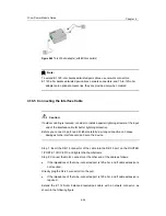
In addition, you may use network connectors to extend T1VI cables.
Note:
Both T1VI cables and network connectors are optional accessories. They are provided only when
ordered.
4.17.5 Connecting the Interface Cable
Caution:
If outdoor cabling is involved, consider to install a special lightning arrester at the input
end of the interface cable for better lightning protection.
Before you connect a port, read its label carefully; a wrong connection can cause
damages to the interface card and even the device.
Step 1: Insert one end of the T1VI cable into the DB-15 port on the ROUTER 1-PORT
T1 VOICE FIC.
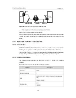
Step 2: Connect the other end of the cable to another device directly or after extending
the cable as shown in the following figure:
Router
Voice D
e
vic
e
Network connector
RJ-45 Straight-through cable
RJ-45
T1VI cable
Router
Voice D
e
vic
e
DB-15
Network connector
T1VI cable
Router
Voice D
e
vic
e
Network connector
RJ-45 Straight-through cable
RJ-45
T1VI cable
Router
Voice D
e
vic
e
DB-15
Network connector
T1VI cable
Figure 4-58
Extending a T1VI cable
Step 3: Power on the router, and check the behavior of the LINK LED on the card
panel: OFF means fault occurs on the line. Check it for the cause.


