3Com Router Module Guide
Chapter 4
4-31
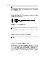
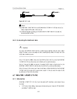
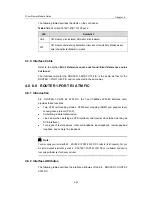
BNC connector
SMB connector
BNC connector
SMB connector
BNC connector
SMB connector
BNC connector
SMB connector
BNC connector
SMB connector
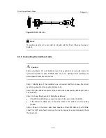
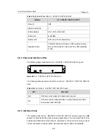
Figure 4-31
E3/T3 cable
Note:
The ROUTER 1-PORT CE3 FIC and the ROUTER 1-PORT CT3 FIC use the same
cable, called E3/T3 cable in this manual.
The standard equipping package of the ROUTER 1-PORT CE3 FIC includes the
required interface cable.
4.6.5 Connecting the Interface Cable
Caution:
By design, the ROUTER 1-PORT CE3 FIC is protected against lightning strikes. But when outdoor
cabling is involved, you are recommended to add a special lightning arrester at the input end of the
E3/T3 cable for better protection.
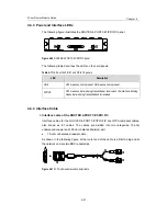
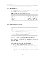
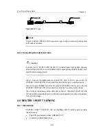
Step 1: Connect the SMB connector of an E3/T3 cable to the Tx port on the ROUTER
1-PORT CE3 FIC and the other end to the Rx port on another device.
Step 2: Connect the SMB connector of another E3/T3 cable to the Rx port on the
ROUTER 1-PORT CE3 FIC and the other end to the Tx port on another device.
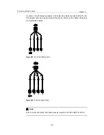
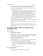
Step 3: Power on the router, and check the behavior of the LINK LED on the ROUTER
1-PORT CE3 FIC panel: OFF means fault occurs on the line and the signal is not
synchronized. Check the line status.
4.7 ROUTER 1-PORT CT3 FIC
4.7.1 Introduction
ROUTER 1-PORT CT3 FIC, the 1-port channelized T3 interface card, delivers these
functions:
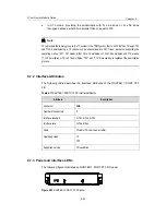
z
In T3 mode, transmitting, receiving, and processing one channel of T3 fast traffic;
providing T3 traffic access.


