3Com Router Module Guide
Chapter 4
4-24
In addition, you are available with 75-ohm-to-120-ohm adapters.
4.4.5 Internal DIP Switch
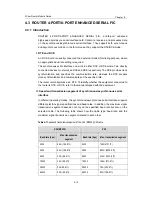
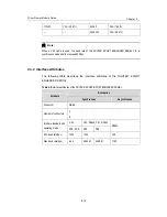
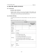
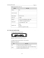
The FIC-E1 and the FIC-E1-F cards provide internal DIP switches, the setting of which
decides interface impedance and the grounding mode.
Table 4-12
DIP switches and E1 interfaces of the FIC-E1/FIC-E1-F cards
Card
ROUTER 4-PORT CE1/PRI FIC
DIP
switch
S1 S2 S3 S4
Controlled E1
interface
Interfa
ce 0
Interfa
ce 1
Interfa
ce 2
Interfa
ce 3
4.4.6 Connecting the Interface Cable
Caution:
Before you connect a port, read its label carefully; a wrong connection can cause
damages to the interface card and even the device.
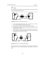
If outdoor cabling is involved, consider to install a special lightning arrester at the input
end of the interface cable for better lightning protection.
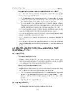
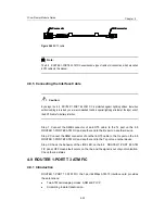
I. Connecting the interface cable of the ROUTER 4-PORT CE1/PRI FIC
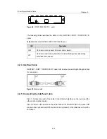
Step 1: Identify type of the E1 cable, and set the DIP switch for the to-be-connected
E1/FE1 port correctly.
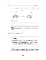
Step 2: Plug the DB-15 connector of the E1 cable into the E1/FE1 port on the card.
Step 3: Connect the other end of the E1 cable to another device.
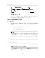
1) When using a 75-ohm unbalanced coaxial cable, do the following:
z
If no cable extension is needed, directly connect the BNC connector of the cable
to the device.
z
If cable extension is needed, connect the BNC connector of the cable to a coaxial
connector, and then connect the other end of the coaxial connector to the device
using a 75-ohm E1 trunk cable.


