3Com Router Module Guide
Chapter 3 Multifunctional Interface Modules
3-57
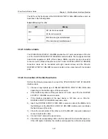
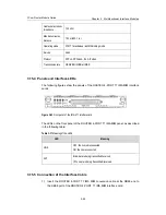
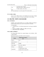
The LEDs on the front panel of the ROUTER 4-PORT E1 IMA MIM interface card, as
described in the following table:
Table 3-35
Meaning of the LEDs
LED
Meaning
LINK
OFF: the link is disconnected.
ON: the link is connected.
ACT
Blink: data is being transmitted/received.
Off: no data is being transmitted/received.
3.14.5 Interface Cable
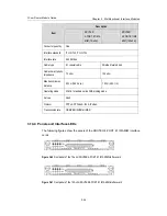
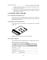
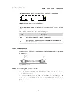
The RT-ROUTER 4-PORT E1 IMA MIM provides four E1 ports and adopts a 120-ohm
or a 75-ohm ROUTER 4-PORT E1 IMA MIM conversion cable. The two types of cables
have similar appearance. Both of them have a DB68 connector at one end used to
connect a router. While at the other end, the 75-ohm ROUTER 4-PORT E1 IMA MIM
conversion cable can be connected with eight coaxial cables; and the 120-ohm
ROUTER 4-PORT E1 IMA MIM conversion cable can be connected with four twisted
pairs.
3.14.6 Connection of the Interface Cable
Perform the following procedure to connect the RT-ROUTER 4-PORT E1 IMA MIM
interface cable:
1) Choose an appropriate type of IMA-8E1/ROUTER 4-PORT E1 IMA MIM cable
depending on the interface type of the peer device.
z
If the interface impedance of the peer device is 75 ohm, use a 75-ohm
ROUTER
4-PORT E1 IMA MIM conversion cable.
z
If the interface impedance of the peer device is 120 ohm, use a 120-ohm
ROUTER 4-PORT E1 IMA MIM conversion cable.
2) Insert the ROUTER 4-PORT E1 IMA MIM conversion cable at the DB68 end to
the DB68 port of the ROUTER 4-PORT E1 IMA MIM interface card, and fasten
the fixed screws of the cable.
3) Check the serial number of the other end of the IMA-4E1 conversion cable and
connect it with an E1 cable.
4) Connect the E1 cable with a peer device.
5) Check the slot-corresponding LED on the front panel of the router after power-on.
If the LED lights, it indicates the interface card passed the self test and operates


