3B SCIENTIFIC PHYSICS 1003307 Скачать руководство пользователя страница 6

2


Never short the fuse or the fuse holder.    


Never cover the air vents in the housing. This is 
necessary in order to ensure sufficient circula-
tion of air required for cooling the internal com-
ponents of the equipment.    


The equipment may only be opened/repaired by 
qualified and trained personnel.   

The 500 V output can be dangerous to touch. 


Switch off the equipment to start with while the 
experiment is set up. 


Any changes to the circuit may only be made 
with the equipment switched off. 
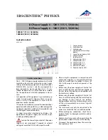
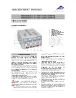
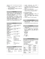
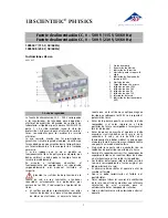
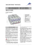


2. Description  

The 0 – 500 V DC power supply provides four inde-
pendently adjustable DC voltages, and is especially 
intended for operating electron tubes, including 
Helmholtz coils. 

The DC voltages are stabilised and regulated, floating 
and galvanically isolated from one another, short 
circuit proof and secure from external voltages The 
output voltages are shown by four analogue displays. 

The DC power supply 1003307 is for operation with a 
mains voltage of 115 V (±10%), and the unit 1003308 
is for operation with a mains voltage of 230 V 
(±10%). 


3. Technical data  

500 V output: 

Voltage: 

0 - 500 V DC, max. 50 mA 

Stability at full load: 


0.01 % ± 100 mV 

Residual ripple: 


20 mV 

50 V output: 

Voltage: 

0 - 50 V DC, max. 50 mA 

Stability at full load: 


0.1 % ± 30 mV 

Residual ripple: 


5 mV 

8 V output: 

Voltage: 

0 - 8 V DC, max. 3 A 

Stability at full load: 


0.1 % ± 30 mV 

12 V output: 

Voltage: 

0 - 12 V DC, max. 4 A 

Stability at full load: 


0.1 % ± 30 mV 

Mains voltage: 

see rear of housing 

Primary fuse: 

see rear of housing 

Displays: 

analogue, class 2 

Terminals: 

4 mm safety sockets 

Power consumption: 

50 VA 

Dimensions: 85x325x190 

mm

 approx. 

Weight: 

4 kg approx. 


4. Operation  

4.1 General information 


Before switching on the DC power supply, set all four 
voltage regulators to zero (turn fully to the left). 


Connect the power supply to the experimental setup. 


Do not switch the power supply on until the 
experiment has been fully assembled. 


Changes to the experimental setup must only be 
made with the power supply switched off. 


Set the required voltages. 


Before switching off the DC power supply, set the 
voltage regulators to zero again (turn fully to the left). 


4.2  Changing the fuse 


Turn off the power switch and unplug the mains plug. 


Unscrew the fuse holder on the rear side of the 
housing with a screwdriver. 


Replace the fuse and reinsert the holder in its socket. 


5. Care and maintenance 


Before cleaning the equipment, disconnect it 
from its power supply. 


Use a soft, damp cloth to clean it. 


6. Disposal 


The packaging should be disposed of at local 
recycling points. 


Should you need to dispose of the equipment 
itself, never throw it away in normal domestic 
waste. Local regulations for the disposal of elec-
trical equipment will apply. 
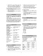
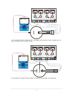
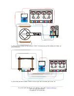
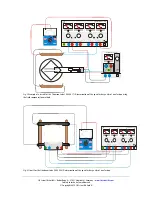
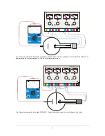
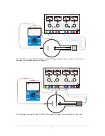
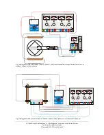
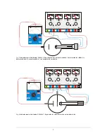
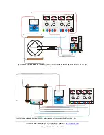


7. Examples of use 

The 0 – 500 V DC power supply is especially suitable 
for use as a voltage source with the following tubes: 

1. Fine beam tube 


             1000904 

2. Training oscilloscope 


             1000902 

3. Dual pole tube  


             1008521 

4. Electron tubes in the S and D tube ranges 


Содержание 1003307

Страница 1: ...häden ist das Gerät unverzüglich außer Betrieb zu setzen In Schulen und Ausbildungseinrichtungen ist der Betrieb des Gerätes durch geschultes Personal ver antwortlich zu überwachen Achtung Die Niederspannungsausgänge des Netzgeräts sind nicht spannungsfest bei externem Anlegen von Spannungen über 500 V gegen Erdpo tenzial Beim Einsatz in experimentellen Aufbauten mit anderen Spannungsquellen z B z...

Страница 2: ...itsbuchsen Leistungsaufnahme 50 VA Abmessungen ca 85x325x190 mm3 Masse ca 4 kg 4 Bedienung 4 1 Allgemeine Hinweise Vor dem Einschalten des Netzgeräts alle Span nungssteller auf 0 stellen linker Anschlag ExperimentellenAufbau mitdemNetzgerätverbinden Netzgerät erst einschalten wenn der Ver suchsaufbau fertig gestellt ist Änderungen am Versuchsaufbau dürfen nur im stromlosen Zustand vorgenommen werd...

Страница 3: ...der Diode S 1000613 Abhängigkeit des Anodenstroms IA von der Heizspannung UF und Nachweis des Anodenstroms IA mit einem Messgerät DC POWER SUPPLY 0 500 V 0 500 V 0 50 V V V V V 0 1 0 0 2 0 03 0 0 4 0 0 5 0 0 0 12 V 0 8 V 0 1 0 2 0 3 0 4 0 5 0 0 2 4 6 8 0 3 6 9 1 2 _ UA UF UG Fig 2 Beispielhafte Beschaltung der Triode D 1000647 Aufnahme des Kennlinienfeldes einer Röhrentriode ...

Страница 4: ... 4 0 5 0 0 2 4 6 8 0 3 6 9 1 2 A Z A DC POWER SUPPLY 0 5 kV KV 0 1 2 3 4 5 0 5 KV Z Fig 3 Beispielhafte Beschaltung der Thomson Röhre S 1000617 Bestimmung der spezifischen Ladung des Elektrons e m mittels Feldausgleich DC POWER SUPPLY 0 500 V 0 500 V 0 50 V V V V V 0 1 0 0 2 0 03 0 0 4 0 0 5 0 0 0 12 V 0 8 V 0 1 0 2 0 3 0 4 0 5 0 0 2 4 6 8 0 3 6 9 1 2 Fig 4 Beschaltung der Fadenstrahlröhre 1000904...

Страница 5: ...mage the equipment should be switched off immediately and secured against any unintended use In schools and other educational institutions the operation of the power supply unit must be super vised by qualified personnel Caution the low voltage outputs of the power supply are not surge proof if exposed to external voltages of more than 500 V with respect to earth When using the equipment in conjun...

Страница 6: ...ability at full load 0 1 30 mV Mains voltage see rear of housing Primary fuse see rear of housing Displays analogue class 2 Terminals 4 mm safety sockets Power consumption 50 VA Dimensions 85x325x190 mm3 approx Weight 4 kg approx 4 Operation 4 1 General information Before switching on the DC power supply set all four voltage regulators to zero turn fully to the left Connect the power supply to the...

Страница 7: ...1 0 2 0 3 0 4 0 5 0 0 2 4 6 8 0 3 6 9 1 2 UA UF Fig 1 Example of a circuit for the diode S 1000613 Determining dependency of anode current IA on filament voltage UF and confirmation of anode current IA using a meter DC POWER SUPPLY 0 500 V 0 500 V 0 50 V V V V V 0 1 0 0 2 0 03 0 0 4 0 0 5 0 0 0 12 V 0 8 V 0 1 0 2 0 3 0 4 0 5 0 0 2 4 6 8 0 3 6 9 1 2 _ UA UF UG Fig 2 Example of a circuit for the tri...

Страница 8: ...2 4 6 8 0 3 6 9 1 2 A Z A DC POWER SUPPLY 0 5 kV KV 0 1 2 3 4 5 0 5 KV Z Fig 3 Example of a circuit for the Thomson tube S 1000617 Determination of the specific charge e m of an electron using the field compensation method DC POWER SUPPLY 0 500 V 0 500 V 0 50 V V V V V 0 1 0 0 2 0 03 0 0 4 0 0 5 0 0 0 12 V 0 8 V 0 1 0 2 0 3 0 4 0 5 0 0 2 4 6 8 0 3 6 9 1 2 Fig 4 Circuit for the fine beam tube 10009...

Страница 9: ...ilisation de l appareil dans les écoles et centres de formation doit être contrôlée par du personnel qualifié sous la responsabilité de ce dernier Attention Les sorties basse tension de l alimentation ne résistent pas à des tensions extrêmes dont le potentiel est supérieur à 500 V par rapport à la terre En cas d utilisation dans des montages expérimentaux avec d autres sources de tension par exemp...

Страница 10: ...uissance absorbée 50 VA Dimensions env 85x325x190 mm3 Masse env 4 kg 4 Manipulation 4 1 Remarques générales Positionner tous les boutons de réglage de tension sur 0 avant de brancher l alimentation butée gauche Raccorder le montage expérimental à l alimentation Ne brancher l alimentation que lorsque le montage expérimental est prêt Toute modification du montage expérimental doit impérativement êtr...

Страница 11: ...elation entre le courant anodique IA et la tension de chauffage UF et démonstration du courant anodique IA à l aide d un instrument de mesure DC POWER SUPPLY 0 500 V 0 500 V 0 50 V V V V V 0 1 0 0 2 0 03 0 0 4 0 0 5 0 0 0 12 V 0 8 V 0 1 0 2 0 3 0 4 0 5 0 0 2 4 6 8 0 3 6 9 1 2 _ UA UF UG Fig 2 Connexion exemplaire de la triode D 1000647 Enregistrement du réseau de caractéristiques d une triode ...

Страница 12: ... 0 5 0 0 2 4 6 8 0 3 6 9 1 2 A Z A DC POWER SUPPLY 0 5 kV KV 0 1 2 3 4 5 0 5 KV Z Fig 3 Connexion exemplaire du tube de Thomson S 1000617 Détermination de la charge spécifique de l électron e m par compensation de champ DC POWER SUPPLY 0 500 V 0 500 V 0 50 V V V V V 0 1 0 0 2 0 03 0 0 4 0 0 5 0 0 0 12 V 0 8 V 0 1 0 2 0 3 0 4 0 5 0 0 2 4 6 8 0 3 6 9 1 2 Fig 4 Connexion du tube à pinceau étroit 1000...

Страница 13: ... apparecchio Attenzione Le uscite di bassa tensione dell alimentatore non sono resistenti alla tensione in caso di applicazione esterna di tensioni superiori a 500 V contro il potenziale di terra In caso di utilizzo in strutture sperimentali con altre sorgenti di tensione ad es per il funzionamento di tubi elettronici accertarsi che sull uscita non siano presenti tensioni superiori a 500 V contro ...

Страница 14: ...m3 Peso ca 4 kg 4 Comandi 4 1 Indicazioni generali Prima di accendere l alimentatore impostare tutti i regolatori di tensione su 0 battuta sinistra Collegare la struttura sperimentale all alimentatore Accendere l alimentatore solo quando la struttura per l esperimento è pronta Le modifiche alla struttura dell esperimento devono essere eseguite solo in assenza di corrente Impostare le tensioni desi...

Страница 15: ...000613 Rapporto di dipendenza della corrente anodica IA dalla tensione di accensione UF e misurazione della corrente anodica IA DC POWER SUPPLY 0 500 V 0 500 V 0 50 V V V V V 0 1 0 0 2 0 03 0 0 4 0 0 5 0 0 0 12 V 0 8 V 0 1 0 2 0 3 0 4 0 5 0 0 2 4 6 8 0 3 6 9 1 2 _ UA UF UG Fig 2 Cablaggio di esempio del triodo D 1000647 Registrazione del campo di caratteristiche di un triodo a tubo ...

Страница 16: ...4 6 8 0 3 6 9 1 2 A Z A DC POWER SUPPLY 0 5 kV KV 0 1 2 3 4 5 0 5 KV Z Fig 3 Cablaggio di esempio del tubo di Thomon S 1000617 Determinazione della carica specifica dell elettrone e m mediante compensazione del campo DC POWER SUPPLY 0 500 V 0 500 V 0 50 V V V V V 0 1 0 0 2 0 03 0 0 4 0 0 5 0 0 0 12 V 0 8 V 0 1 0 2 0 3 0 4 0 5 0 0 2 4 6 8 0 3 6 9 1 2 Fig 4 Cablaggio del tubo a fascio elettronico 10...

Страница 17: ...ablemente por personal instruido al respecto Atención Las salidas de baja tensión de la fuente de red no son resistentes a tensiones conectadas externamente con potenciales por encima de los 500 V con respecto al potencial de tierra Al realizar montajes experimentales con otras fuentes de tensión p ej para el funcionamiento de tubos de electrones es necesario tener en cuenta que en la salida no se...

Страница 18: ... Antes de conectar la fuente de tensión se ponen en 0 todos los ajustes de las tensiones extremo izquierdo Se interconecta el montaje experimental con la fuente de alimentación Se conecta la fuente de alimentación sólo cuando el montaje experimental ya esté listo Cambios el montaje experimental se deben realizar sólo con el circuito sin corriente Se ajustan las tensiones deseadas Antes de desconec...

Страница 19: ...0613 Dependencia de la corriente anódica IA de la tensión de caldeo UF y demostración de la corriente anódica IA con un aparato de medición DC POWER SUPPLY 0 500 V 0 500 V 0 50 V V V V V 0 1 0 0 2 0 03 0 0 4 0 0 5 0 0 0 12 V 0 8 V 0 1 0 2 0 3 0 4 0 5 0 0 2 4 6 8 0 3 6 9 1 2 _ UA UF UG Fig 2 Cableado especial del triodo D 1000647 Registro de las características de un triodo de tubo ...

Страница 20: ...0 5 0 0 2 4 6 8 0 3 6 9 1 2 A Z A DC POWER SUPPLY 0 5 kV KV 0 1 2 3 4 5 0 5 KV Z Fig 3 Cableado especial del tubo de Thomson S 1000617 Determinación de la carga específica del electrón B e m por medio de compensación de campo DC POWER SUPPLY 0 500 V 0 500 V 0 50 V V V V V 0 1 0 0 2 0 03 0 0 4 0 0 5 0 0 0 12 V 0 8 V 0 1 0 2 0 3 0 4 0 5 0 0 2 4 6 8 0 3 6 9 1 2 Fig 4 Cableado del tubo de haz fino 100...

Страница 21: ...aparelho deve ocorrer sob a responsabilidade de pessoas preparadas para a operação do aparelho Atenção As saídas de baixa tensão da fonte de alimentação não tem estabilidade tensional em caso de aplicações de tensões acima de 500 V contra o potencial de terra Na utilização em montagens experimentais com outras fontes de tensões p ex para a operação de tubos eletrônicos sempre ter cuidado que na sa...

Страница 22: ...ção 4 1 Indicações gerais Antes de ligar o aparelho levar todos os botões de ajuste de tensão ao zero bloqueio à esquerda Conectar a montagem experimental com o aparelho fonte de alimentação Só ligar o aparelho fonte de alimentação quando a montagem experimental estiver completamente montada Só é permitido efetuar alterações na montagem da experiência enquanto a corrente estiver desligada Ajustar ...

Страница 23: ...13 Dependência da corrente anódica IA da tensão de aquecimento UF e com provação da corrente anódica IA com um aparelho de medição DC POWER SUPPLY 0 500 V 0 500 V 0 50 V V V V V 0 1 0 0 2 0 03 0 0 4 0 0 5 0 0 0 12 V 0 8 V 0 1 0 2 0 3 0 4 0 5 0 0 2 4 6 8 0 3 6 9 1 2 _ UA UF UG Fig 2 Conexão exemplar do triodo D 1000647 Registro das linhas campo para reconhecimento de um tubo tríodo ...

Страница 24: ...0 4 0 5 0 0 2 4 6 8 0 3 6 9 1 2 A Z A DC POWER SUPPLY 0 5 kV KV 0 1 2 3 4 5 0 5 KV Z Fig 3 Conexão exemplar do tubo de Thomson S 1000617 Determinação da carga específica do e m por meio da compensação de campos DC POWER SUPPLY 0 500 V 0 500 V 0 50 V V V V V 0 1 0 0 2 0 03 0 0 4 0 0 5 0 0 0 12 V 0 8 V 0 1 0 2 0 3 0 4 0 5 0 0 2 4 6 8 0 3 6 9 1 2 Fig 4 Conexão do tubo de raios catódicos de feixe estr...

Отзывы: