


Copyright © 2014 Linear LLC
1
2GIG-BRDG1-900
GO!BRIDGE IP COMMUNICATOR
INSTALLATION INSTRUCTIONS
The
Go!Bridge
IP
Communicator™
(2GIG
‐
BRDG1
‐
900)
provides
Internet
connectivity
between
the
monitoring
service’s
Central
Station
and
the
Go!Control®
Panel,
when
the
panel
is
used
as
a
household
burglar
alarm
system.
It
supports
automatic
firmware
updates,
provides
interactive
security
services,
and
increases
supervision
using
signal
‐
forwarding
to
the
Central
Station.
For
wireless
communication
with
the
Control
Panel,
the
900MHz
Transceiver
Module
(2GIG
‐
XCVR)
must
be
installed
in
the
panel.
For
Internet
access,
the
Go!Bridge
must
be
connected
to
the
local
network
router
using
an
Ethernet
cable
(not
provided).
Contents
Verify
that
the
package
includes
the
following:
•
1—Go!Bridge
IP
Communicator
•
1—5VDC
USB
Mini
‐
B
Power
Supply
•
1—Stand
•
1—Plastic
Power
Supply
Bracket
(includes
Self
‐
Adhesive
Backing
and
Zip
Tie)
•
1—Wall
Socket
Screw
for
Power
Supply
Bracket
•
2—Phillips
Head
Screws
and
Wall
Anchors
(to
mount
unit
on
wall)
•
4—Self
‐
Adhesive
Vinyl
Bumpers
for
use
on
unit
or
stand
Requirements
Before
you
install,
program,
and
test
the
Go!Bridge
IP
Communicator,
ensure
the
control
panel
being
paired
with
the
Go!Bridge
IP
Communicator
meets
these
requirements:
•
Firmware
Version
1.12
(or
higher)
•
2GIG
‐
XCVR
900
MHz
Transceiver
IMPORTANT:
For
compliance
with
UL
1023:
Household
Burglar
‐
Alarm
System
Units
,
the
Go!Bridge
must
be
installed
in
the
same
room
as
the
Internet
modem
or
router.
NOTE:
To
protect
data
sent
via
the
local
wireless
network,
it
is
recommended
that
you
install
the
Go!Bridge
IP
Communicator
on
a
local
network
where
either
WPA
(Wi
‐
Fi
Protected
Access)
or
WPA2
(Wi
‐
Fi
Protected
Access
II)
encryption
is
already
enabled.
After
installing,
programming,
and
testing
the
Go!Bridge
IP
Communicator,
you
will
need
to
register
a
new
customer
with
the
third
‐
party
monitoring
service.
See
Registration
on
page
3.
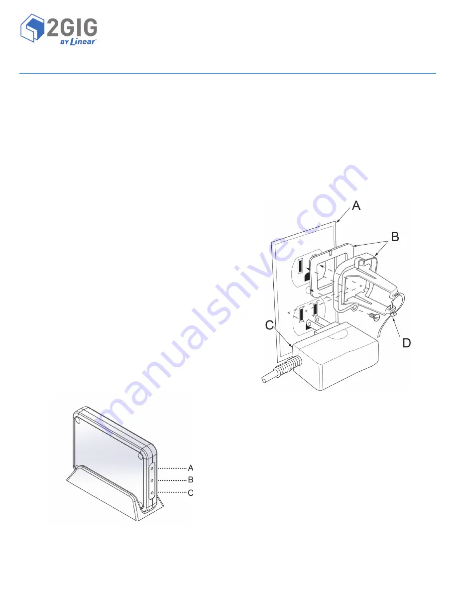
Figure 1
Go!Bridge Front View—LED Indicators and Learn Button
Powering ON the Go!Bridge IP Communicator
Use
these
steps
to
power
ON
the
Go!Bridge
IP
Communicator:
1
Attach
the
power
supply
to
the
bracket
(provided)
as
follows:
1a
Insert
the
power
supply
into
the
enclosure
on
the
plastic
bracket.
See
C
in
the
figure
below.
1b
Secure
the
power
supply
to
the
retaining
bracket
by
threading
a
zip
tie
through
the
bracket’s
slots.
See
D
in
the
figure
below.
1c
Remove
the
strip
from
the
self
‐
adhesive
backing
on
the
power
supply
bracket.
1d
Affix
the
adhesive
on
the
bracket
to
the
wall
outlet.
Then
secure
the
bracket
to
the
outlet
with
the
wall
socket
screw
(provided).
NOTE:
Always
use
the
provided
power
supply
bracket
in
the
United
States
(and
other
countries
where
it
is
required).
Canada
does
not
require
the
power
supply
retaining
bracket.
Figure 2
Power Supply and Bracket
2
Connect
the
Go!Bridge
to
the
power
source.
NOTE:
Do
not
connect
an
Ethernet
cable
to
the
Go!Bridge
IP
Communicator
at
this
time.
You
will
connect
the
cable
when
completing
the
steps
in
Programming
the
Go!Bridge
IP
Communicator
into
the
Control
Panel
.
3
(Optional)
Place
the
stand
(provided)
on
a
counter,
desktop,
or
other
flat
surface.
Set
the
Go!Bridge
IP
Communicator
in
the
stand.
NOTE:
To
protect
surfaces
from
damage,
affix
the
self
‐
adhesive
vinyl
bumpers
to
the
unit
or
stand.
4
Verify
that
the
two
(2)
LEDs
on
the
Go!Bridge
IP
Communicator
illuminate
in
RED.
See
Figure
1
Go!Bridge
Front
View—LED
Indicators
and
Learn
Button
on
page
1.
A
Network
LED
B
900
MHz
LED
C
Learn
Button
A
110V
Wall
Outlet
B
Plastic
Power
Supply
Bracket
with
Adhesive
Backing
C
AC
Power
Supply
D
Zip
Tie


