19 Zoll-Tec AI-7100ULD Скачать руководство пользователя страница 29

LCD KVM Console User Manual

29

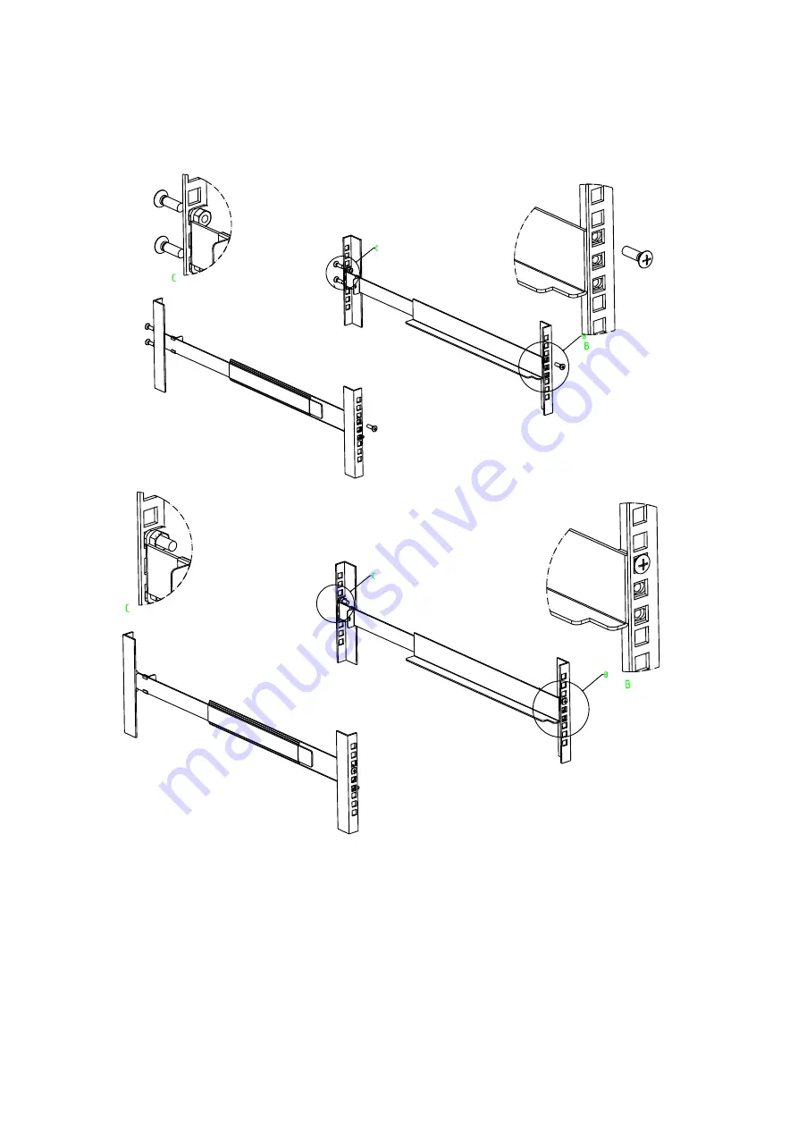
Built-in mounting bracket installing (All ULS/TLS/DLS Serial products):

The built-in mounting bracket comes with a nut, and the fixing nut is welded inside the bending hole at

the top of the bracket. Install the bracket into the cabinet mounting post on the upper cabinet, align the

bracket mounting holes with the holes in the cabinet mounting column, and then use the screws to fix.

Place the KVM Switch in the installed bracket and secure the KVM Switch, cabinet and mounting

bracket.

Содержание AI-7100ULD

Страница 1: ...AS 7100 AS 9100 series Single Dual Rail LCD KVM SWITCH User Manual 19 Zoll Tec GmbH Berlinstraße 19 55411 Bingen Germany phone 0049 0 6721 3092601 email info 19zoll tec de ...

Страница 2: ...e will not occur in a particular installation If the equipment is turned on or off causing interference to radio and television reception the user should try the following to reduce the interference Change the direction and move the receiving antenna Increase the distance between the equipment and the receiver Connect the device to the circuit outlet not the interface to which the receiver is conn...

Страница 3: ...personally The manufacturer will not be liable for any damage resulting from incorrect selection of the operating voltage before operation Please be sure that the voltage has been set correctly before use A typical LCD liquid crystal display has millions of pixels A dead pixel is a defective pixel that does not display the correct color On the screen it usually looks like a tiny black or white dot...

Страница 4: ...e cascaded AS 7108TLS CAT5 8Ports KVM 17inch 4 3 LCD Monitor OSD Menu Demountable Structure Can be cascaded AS 7108DLS DVI 8Ports KVM 17inch 4 3 LCD Monitor OSD Menu Demountable Structure AI 7108ULS VGA 8Ports KVM 17inch 4 3 LCD Monitor OSD Menu Demountable Structure Can be cascaded IP Remote Control AI 7108TLS CAT5 8Ports KVM 17inch 4 3 LCD Monitor OSD Menu Demountable Structure Can be cascaded I...

Страница 5: ...enu Demountable Structure Can be cascaded AS 7108TLD CAT5 8Ports KVM 17inch 4 3 LCD Monitor OSD Menu Demountable Structure Can be cascaded AI 7108ULD VGA 8Ports KVM 17inch 4 3 LCD Monitor OSD Menu Demountable Structure Can be cascaded IP Remote Control AI 7108TLD CAT5 8Ports KVM 17inch4 3 LCD Monitor OSD Menu Demountable Structure Can be cascaded IP Remote Control AS 9108ULD VGA 8Ports KVM 19inch4...

Страница 6: ...ion Guide 1 pc Quick installation manual Mounting brackets 2 pcs LCD KMV Single mounting bracket Lock ear 2 pcs LCD KVM fix the rear panel Install the screw kit 1 pc Screw the mounting bracket Check that all parts are present and that they are not damaged in transit If you encounter problems contact your dealer To prevent damage to the machine or equipment connected to the machine please read this...

Страница 7: ...allation 26 Stacking and Installation Precautions 26 Standard Rack Mounting 28 KVM Modules Assembly Removal 32 Removal of the Keyboard Module 33 Expansion Module Installation 34 Single Device Installation 37 Installation of Single Port LCD KVM Switch 40 Cascade Device Connection 43 Chapter3 46 Basic Operation 46 Hot Plug 46 Hot Plug Computer Connection 46 Hot Plug Console Port 46 Connection Port S...

Страница 8: ...DE 57 CHANNEL DISPLAY DURATION 57 CHANNEL DISPLAY POSITION 57 SCAN DURATION 58 SET PASSWORD 58 SET SUPER PASSWORD 58 CLEAR THE NAME LIST 59 RESTORE DEFAULT VALUE 59 LOCK CONSOLE 59 Appendix 60 Safety Instructions 60 General 60 Rack mounting 61 Product Specifications 62 LCD Module Specifications 65 Warranty Conditions 66 ...

Страница 9: ...bes and introduces the front and rear panel components Chapter 2 Hardware Installation This section describes how to install the product and the necessary steps including basic stand alone installation multi switch level connection installation and IP module expansion installation Chapter 3 Basic Operation Explain the basic operating concepts of the KVM switch Chapter 4 OSD Operation Provides a co...

Страница 10: ...joined by a plus sign E g Ctrl Alt 1 Numbers indicate the actual operating sequence numbers The diamond symbol indicates that the information is provided for reference but is not relevant to the procedure The origin symbol indicates the sorting sub item information independent of the operation steps Indicates the most important information Product Information To find out more about KVM s products ...

Страница 11: ...peration even in the KVM above the computer This product is very fast and easy to install just simply connect the cable to the appropriate connection Port no software settings no cumbersome installation procedures and there will be no incompatibility issues As the device can directly access the keyboard input data it can operate in a variety of operating platforms compatible PC Mac Sun etc As it a...

Страница 12: ...al 12 components to facilitate the free combination of different applications According to the module type can be divided into three categories VGA device type DVI device type CAT5 type Port number can be divided into 1 4 8 16 ...

Страница 13: ...afari Opera Mozilla Netscape etc You can upgrade the remote network control mode through the extended IP board Support OSD to set user login mode and increase KVM login security requirements Support high video resolution in local and remote IP mode Support 480i 480p 720p 1080i and 1080p 1920 1200 Support wide screen resolution Extended IP remote control mode supports 1000M Ethernet control transmi...

Страница 14: ...A set of USB interface keyboard Single ended extension cable optional IP remote control terminal 1000M network interface optional installation Computer The following devices must be installed on each computer A VGA or DVI video display card USB Type A connection port PS2PS2 keyboard mouse Port Cables KVM equipment provides six kinds of connection cables according to the user s use to choose LCD KV...

Страница 15: ...se green VGA USB Type A PS2 Keyboard Purple PS2 Mouse Green DVI I USB Type A Audio KVM connection Computer connection Note The cable length affects the quality of the display If you need other lengths of cable contact the merchant you purchased to purchase a cable suitable for this switch ...

Страница 16: ...8 Vista 7 10 Linux RedHat 9 0 or higher Fedora and above RHEL AS 4 RHEL 5 SuSE 10 11 1 OpenSUSE 10 2 SLES 10 SP1 Debian 3 1 4 0 Ubuntu 7 04 7 10 UNIX AIX 4 3 or higher FreeBSD 5 5 or higher Sun Solaris 8 or higher Mac OS 9 0 to 10 6 Snow Leopard Novell Netware 6 0 or higher DOS 6 2 or later More operating system support please pay more attention to the latest version of the relevant product compat...

Страница 17: ...ion please see the figure after the serial number table describes the details No Part Function Description 1 Upper handle Pull the handle slide the LCD module out and push it in 2 Lock Used to lock the LCD module pull out the module must first unlock push into the automatic locking 3 LCD screen cover Can be opened or closed with the handle opening and closing ...

Страница 18: ...LCD module sliding track can be telescopic freely 10 Keyhole Corresponds to the latch of the LCD module 11 LCD Keypad Panel Used to control the LED screen display adjustment and switch 12 Front USB Used to access an external USB keyboard or mouse Rear view The Rear View of this product series is a rear view of the Removable KVM Switch Module and the functional description of each Hardware Port ref...

Страница 19: ...ivided into 4 models according to the number of ports single port 4 ports 8 ports 16 ports In addition the control module of Remote Control IP can be selected according to the needs CAT5 Port This type of LCD KVM switch can be divided into 3 models according to the number of ports 4 ports 8 ports 16 ports in addition can be optional Remote Control IP control module DVI Port This type of LCD KVM sw...

Страница 20: ...LCD KVM Console User Manual 20 Single rail Dual rail LCD Console display Front view of the 4 3 screen and 16 9 screen single rail 17inch 4 3 screen 19inch 16 9 screen ...

Страница 21: ...LCD KVM Console User Manual 21 Front view of the 4 3 screen dual rail 17inch 4 3 screen 19inch 4 3 screen ...

Страница 22: ...LCD KVM Console User Manual 22 Dual Rail Slide View Dual rail overall rear view ...

Страница 23: ...LCD KVM Console User Manual 23 Overall Dimensions of the LCD KVM Single rail single port KVM Console dimension ...

Страница 24: ...LCD KVM Console User Manual 24 Single rail multi ports KVM Console dimension ...

Страница 25: ...LCD KVM Console User Manual 25 Dual rail LCD KVM Console dimension ...

Страница 26: ...rotect the product Attach the protective film and filler to the LCD module and remove the filler before mounting The LCD KVM switch can be placed in any suitable plane and is sufficient to securely support the weight of the equipment plus additional cables Please make sure that the plane is clean and free from other debris that can affect the ventilation and normal operation of the switch INSTALLA...

Страница 27: ...LCD KVM Console User Manual 27 Slide the switch onto the support flanges Use the screws supplied with this package to loosely attach the front of the switch to the front of the rack ...

Страница 28: ...sole User Manual 28 Slide the rear attachment sliding brackets along the slide bars until they contact the rear of the switch Use the screws supplied with this package to attach the bars to the rear of the switch ...

Страница 29: ...e fixing nut is welded inside the bending hole at the top of the bracket Install the bracket into the cabinet mounting post on the upper cabinet align the bracket mounting holes with the holes in the cabinet mounting column and then use the screws to fix Place the KVM Switch in the installed bracket and secure the KVM Switch cabinet and mounting bracket ...

Страница 30: ...LCD KVM Console User Manual 30 Mounting and fixing in the bracket tail ...

Страница 31: ...e User Manual 31 Screws mounting position instruction Note There may be a difference between the two rail mounting bracket and the single slide carriage For the dual rail product please refer to the following figure ...

Страница 32: ...er for repair and replace Please refer to the figure for loading and unloading operations 1 Now put this series of products on the appropriate operating platform ready for Screwdriver tools for subsequent use of removable screws Remove the KVM assembly and the captive screws on the side brackets as shown to separate the KVM assembly from the front LCD assembly 2 3 Please note the connector between...

Страница 33: ...or repair this part can also be demolished according to the following diagram 1 The LCD KVM placed in the rack and fixed the LCD panel turned up revealing the keyboard the mouse s operating surface 2 The bottom of the keyboard panel has a circular hole you can use your fingers through the circular hole the top of the keyboard ...

Страница 34: ... side the keyboard could be taken out Thus completing the demolition of the keyboard module Note If you replace the installation please first plug the keyboard USB interface then put the keyboard module into the limit slot Expansion Module Installation If you buy a KVM switch because you need to increase the remote control and operation you can directly ...

Страница 35: ...gement of KVM Application ability 1 find the rear of the device expansion slot outside the blank position for installation you need to prepare a screwdriver for removal and installation tools 2 Before installation use a screwdriver to remove the two fixing screws on the blank 1 Remove the blank after you can see the need to expand the installation of the IP module placement cavity keep the screw r...

Страница 36: ...dule with the two screws that have been removed before 4 After installing the IP module you need to follow the instructions of the IP module To install the software and configure the IP address of the device before you can connect the network cable to the switching device After the installation is complete you can access the network to log in For details refer to the IP module s product manual ...

Страница 37: ...B or PS2 connector of the KVM cable into the corresponding port on the PC 4 Plug the power adapter supplied with this package into the AC power source and plug the other end of the power adapter into the power jack on the switch 5 Connect the network cable to the IP port of the IP module 6 Turn on the computer Note 1 Make sure that all plugs are connected to the same group of KVM connection port j...

Страница 38: ...s are connected to the same group of KVM connection port jacks all connected to Port1 or all connected to Port2 2 The IP module is an optional module of the product If the product you purchased does not include the module please ignore the related operation in Step 5 3 Before using the IP module please make the appropriate configuration and network debugging after the access to the network you wan...

Страница 39: ...ort composite audio plug into the audio jack 4 Connect the AC adapter to the AC power source and plug the other end of the power adapter into the power jack on the switch 5 Connect the network cable to the IP port of the IP module 6 Turn on the computer Note 1 LCD KVM conversion module is divided into two types PS2 and USB port you can connect your computer to choose the appropriate conversion mod...

Страница 40: ...LCD KVM Console User Manual 40 Installation of Single Port LCD KVM Switch ...

Страница 41: ...KVM Console User Manual 41 Single port LCD KVM switch choose KVM cables to connect instead of multi port use KVM module divided into two kinds VGA and DVI according to the port type VGA Single port LCD KVM ...

Страница 42: ...37 port to the corresponding port on the back of the LCD and then connect the video port of the other end to the video port of the computer Then connect the port of PS2 or USB to the corresponding keyboard and mouse port of the computer then power the computer and the LCD KVM switch ...

Страница 43: ...ch Cascade In switch cascade mode the keyboard mouse and computer connections and stand alone connection is the same this part will not repeat them the number part of the description is as follows 1 The cascade KVM switch have two connection methods the use of USB KVM conversion module cable or PS2 KVM conversion module cable and a switch to the next level to connect Refer to the description of th...

Страница 44: ...LCD KVM Console User Manual 44 The connection diagram is shown in the following figure CAT5PortLCD KVM Switch Cascade ...

Страница 45: ...LCD KVM Console User Manual 45 VGALCD KVM Switch Cascade CAT5LCD KVM Switch Cascade ...

Страница 46: ...t plug functionality this feature may not function properly Hot Plug Console Port This product also provides keyboard mouse and display hot plug function This product provides keyboard and mouse port for two interface types Users can select the corresponding device connection type according to their usage and carry out corresponding control operation Note If you access the USB and PS2 keyboard mou...

Страница 47: ... are used for Port selection input the corresponding port number ENT to finish the switch of Port To reset the KVM switch you need to click RST for 3 5 seconds to complete the KVM switch restart OSD Menu Screen Selection LCD OSD Menu key operation AUTO Press the key to set the display setting for the screen to automatically adjust to the resolution MENU Press the key to perform the main function O...

Страница 48: ...urn completed the command transmission KVM switch will switch the corresponding number Of the Port computer If you want to change the key combination of the hotkey you can set and change it in the corresponding option of OSD Menu Power Off and Restart If you need to power off the KVM switch do the following before turning it back on 1 Unplug the power supply to the KVM 2 Turn off all computers con...

Страница 49: ...art of the LCD unit After unlocking the LCD module can be pulled out from the slide rail Refer to the diagram above for operation To open the LCD display screen you can flip the screen upwards to fit the viewing angle only The maximum angle that the LCD screen can be opened is 105 degrees 120 degrees You can view the screen at any angle you like ...

Страница 50: ...h in operation of the LCD module the unlocking action must be done first and the unlocking switch is on both sides of the slide rail Please refer to the figure above for the specific operation After unlocking the LCD assembly can be pushed into the slide rail Note 1 Push the LCD assembly into the slide the unlock action and push action should be careful improper operation may clip your finger 2 Wh...

Страница 51: ...he login password is set successfully the subsequent login requires the correct administrator user password to enter the OSD menu Interface operation When you enter the setting options some functions may need to be edited and modified by the administrator The default administrator password is admin You can also modify and change them as needed OSD Hot Key By default you can type the CTRL key twice...

Страница 52: ... the arrow keys If the number of rows in the list is larger than the number that the screen can display the screen scrolls When the OSD menu is closed a small blue window will appear on the screen showing the port number that is currently switched to OSD Main Screen Headings Heading Explanation PN This column lists the port numbers for all the CPU ports on the installation The simplest method to a...

Страница 53: ...e F1 key to start the GOTO function The GOTO function allows you to switch directly to the connection port by typing the port name or its port number 1 To use NAM method move highlight bar to NAME press Enter input name of a port then press Enter to confirm 2 To use PN method move highlight bar to PN press Enter input port number then press Enter to switch If the port number is invalid it will rem...

Страница 54: ...selected for listing on the main screen with this function The choices and their meanings are given in the table below Choice Meaning ALL Lists all of the ports on the installation QVIEW Lists only the ports that have been selected as Quick View Ports POWERED ON Lists only the ports that have their attached computers powered on POWERED ON QVIEW Lists only the ports that have their attached compute...

Страница 55: ...tes or edits the name of a port Press F5 a pink edit box will appear on the screen Input name and then press Enter the port is set a name and it will also appear on the screen F6 SET SET function settings can be set to the administrator and the user to set the OSD menu The related functions and user rights related settings such as management settings login password display mode switch hotkey adjus...

Страница 56: ...t the option before to indicate that the item has been selected The settings are described in the following table Settings Function OSD ACTIVATING HOTKEY OSD Menu Activates hotkey combination selection settings SWITCH HOTKEY KVM port switch hot key combination selection setting SCAN DURATION Port scan dwell time setting SET PASSWORD User login password settings SET SUPER PASSWORD The administrator...

Страница 57: ...t is to use CTRL CTRL as the OSD menu start hotkey SWITCH HOTKEY It provides you with four hotkey combinations SCRLL SCRLL NUM CTRL CTRL NUM ALT ALT NUM SHIFT SHIFT NUM You can use the keyboard to move cursor to select and then press Enter key to save The default is to use SCRLL SCRLL NUM as the OSD menu start hotkey NUM is the numeric keypad of the keyboard The valid numeric range is 01 16 ...

Страница 58: ...to an option and press Enter to select it SET PASSWORD Set new password First enter old password then enter new password and confirm it The new password is set If error occurs the screen will remind users SET SUPER PASSWORD When setting the administrator password you need to enter the correct password Before new password is updated input the previous password twice the new password to take effect ...

Страница 59: ...ll the OSD menu options to restore the initial settings so please be careful to do this When doing this you need to verify the password of the administrator input Y key then press Enter to confirm the operation To cancel this operation input N key and then press Enter to confirm the cancel operation or keyboard input Esc directly back LOCK CONSOLE You cannot switch or scan after you lock the conso...

Страница 60: ...gned for IT distribution system with 100V 230V phase to phase voltage To prevent damage to your device it is important that all equipment be properly grounded Do not place anything on the power cord or cable and route the power cord and cable routing to avoid tripping over it If the equipment uses an extension cord make sure that the total capacity of all products using the line does not exceed th...

Страница 61: ... rack make sure that the rack is stable and stable Be careful when releasing the latch by pressing the device rails and sliding the unit into the rack The track of the slide rail may clip to your finger After mounting the device to the rack carefully spread the rails to the locked position and then slide the unit into the rack Do not overload the AC supply branch circuit that supplies power to the...

Страница 62: ... Female Blue Power 1 x DC Jack Network Port 1 x RJ45 Switch Connection Port Selection KVM Operation Panel Digital keys KVM Reset KVM Operation Panel Function Keys IP Module Reset 1 x semi embedded key IP Module Default 1 x semi embedded key LED s Selected Nixie Tube Display Online 4 x Red 8 x Red 16 x Red IP Network 1 x Green 1 x Orange Analog Mode Keyboard Mouse USB PS 2 Resolution Max 1920 x 120...

Страница 63: ... 2 Switch Module Port 4 x RJ45 8 x RJ45 16 x RJ45 Power 1 x DC Jack Network Port 1 x RJ45 Switch Connection Port Selection KVM Operation Panel Digital keys KVM Reset KVM Operation Panel Function Keys IP Module Reset 1 x semi embedded key IP Module Default 1 x semi embedded key LED s Selected Nixie Tube LED Display Online 4 x Red 8 x Red 16 x Red IP Network 1 x Green 1 x Orange Analog Mode Keyboard...

Страница 64: ...male 4 x USB Type B Female 8 x USB Type B Female Monitor 1 X DVI 1 4 x DVI I 8 x DVI I Mixed Audio Connector 1 x Mini Stereo Female Black 4 x Mini Stereo Female Black 8 x Mini Stereo Female Black Power 1 x DC Jack Switch Connection Port Selection KVM Operation Panel Digital keys KVM Reset KVM Operation Panel Function Keys LED s Selected Nixie Tube LED Display Online 4 x Red 8 x Red Analog Mode Key...

Страница 65: ...pport color 16 7M color RGB 6 bit Hi_FRC 16 7Mcolor True 8 bit Contrast 1000 1 Typ Backlight LED Pixel spacing 0 264x0 297mm 0 294x0 294mm 300 300um LEDService life 100 000Hours Nominal Input Voltage 5 0V Keyboard Keyboard Layout Ultra thin US100 key Stand alone Removable keyboard Keyboard language format optional Compatible Microsoft Windows9 Me NT 2000 XP WIN7 Server2003 WIN8 WIN10 Port Standard...

Страница 66: ...direct indirect special incidental or consequential damages resulting from the use of this product or the enclosed CD ROM documentation etc The Company makes no warranty express implied or statutory regarding the content and use of this document and specifically disclaims any implied warranties of merchantability fitness for a particular purpose suitability or fitness for a particular purpose ...

Отзывы: