


Bitbox 2.2 User’s Manual
1/30/19 2:45 PM
Copyright 1010music LLC 2019
Page 32 of 39
Digital Heart – Analog Soul
Use MIDI to Trigger Slice Playback
Bitbox also allows you to use MIDI to trigger playback of individual slices within a cell. Here is a basic example of how to do
this:
1.
Create a Slicer Cell and create 4 or more slices by either using the Scan feature or manually creating the slices. One
example of a WAV file to use with this feature is \SFX\Metal\METL_shake and squeal.wav.
2.
Set the following values for the cell parameters:
Parameter
Value
Explanation
LaunchMode
Trigger
This will cause the WAV slice to play from beginning to end
when a trigger is received. Other values will work, but let’s use
this for the example.
Loop Mode
Off
We will turn off looping for this example.
Slice
3
When a MIDI Note on MIDI Channel 10 is received, Slice 3 will
be the starting point for the sequencer. If Seq is disabled, then
Slice 3 will always play.
MIDI
Choose a MIDI Channel
other than 10.
We want to see the difference between the default MIDI
behavior on Channel 10 and using MIDI to trigger slices, so we
need to use a separate channel. MIDI notes received on the
channel you select here will choose a slice to play.
Slice Seq
None
We will not use the Slice Sequencer in this example.
3.
Set up a MIDI input that uses the MIDI Channel you selected for the MIDI parameter. Play MIDI note 36. You will see
that slice 1 is played. Play MIDI Note 39 and slice 4 will be played. MIDI Notes 36 and up are now mapped to Slices
1 and up for playback.
The steps above show a simple example of using MIDI alone to trigger different slices within one cell. You can use this with
Loop Mode ON with Launch Modes of Gate or Toggle to achieve different effects. You could also use this with Slice Seq if you
wanted to have the Slice Seq control what slices play when a cell trigger is received.
Use Control Voltage to Trigger a Row of Cells
You can send a control voltage signal to the right column of
CV Modulators
to trigger all of the cells in the corresponding
row. This is called a Scene Trigger.
1.
Plug a CV signal into the right column of
CV Modulator
jacks. These are the
jacks that map to
EXT1
through
EXT4
.
2.
Touch the corresponding EXT cell and then press
INFO
. Bitbox displays the
External Input Parameters screen.
3.
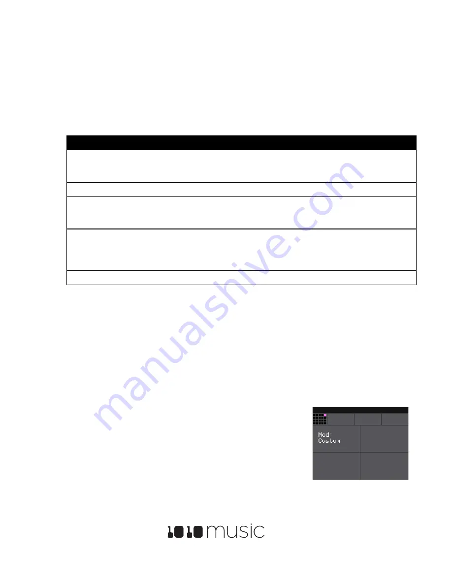
Set the value of the
Mod
parameter to
Scene Trig
.
4.
Send a trigger signal to the configured
CV Modulator
jack. Bitbox will trigger
all of the cells in the row simultaneously.
Figure 32: External Input
Parameters Screen


