background image

505, 8

th

 Avenue, 10

th

 Floor, New York, NY 10018. Tel: 212-9910090 email: [email protected] 
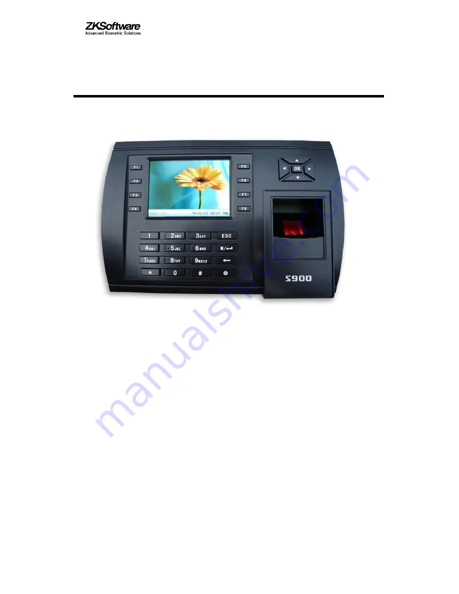
                                                                               

S900 

Time & Attendance 

and 

Access Control Terminal


Installation Instructions 


Revised March 2008 


Summary of Contents for S900

Page 1: ...505 8 th Avenue 10 th Floor New York NY 10018 Tel 212 9910090 email support zk usa com S900 Time Attendance and Access Control Terminal Installation Instructions Revised March 2008 ...

Page 2: ...el 212 9910090 email support zk usa com About this Guide This guide provides installation instructions only For information regarding actual operation and configuration of the S900 Time Attendance and Access Control Terminal refer to the user manual ...

Page 3: ... 9 2 2 3 Alarm connection 9 2 2 4 Door lock connection 11 2 2 5 Ethernet connection 15 2 2 6 RS232 connection 17 2 2 7 RS485 connection 18 2 2 8 Wiegand output connection 19 2 2 9 Connecting with external Weigand reader 20 2 2 10 Power connection 21 3 Miscellaneous Features 22 3 1 Reset 22 3 2 Tamper proof Button 23 3 3 Using USB flash drive 23 3 4 Built in proximity card reader Optional 23 3 5 Bu...

Page 4: ...Possible resulting damage from not powering off the S900 prior to wiring is not covered by manufacturer s warranty 4 Mount the S900 at a comfortable height typically between 4 and 5 feet from the ground 5 After installation remove protective film from the S900 display and fingerprint sensor 6 To prevent being accidentally locked out while testing the exit door button keep a person on the inside of...

Page 5: ...under manufacturer s warranty 11 Only use supplied transformer and cord Do not attempt extending the cord by cutting and splicing 12 If using RS485 mode of communication use only a ZK Software supplied RS485 converters Using a 3rd party RS485 converter may or may not work If the RS485 cable length exceeds 200 feet we recommend using a 120Ώ terminator 13 Refer to the user handbook and operating ins...

Page 6: ... 3 1 System Configuration 1 1Illustration of system configuration ...

Page 7: ...4 1 2 Communication Options The S900 can directly connect with a PC through RS232 or Ethernet The S900 can connect with a PC through RS485 network The S900 can connect with a PC through Ethernet network ...

Page 8: ...ould be mounted on the external wall of the door approximately 4 to 5 feet from the ground After the desired position is determined cut out an opening approximately 1 inch x 1 inch for cables see below figure s shadowed area 3 Line up the opening of the mounting plate with the newly cut out opening on the wall and then screw the plate to the wall 4 After installation make sure the mounting plate i...

Page 9: ...fore connecting peripheral equipment Follow instructions to connect peripheral equipment such as Door sensor connection Exit button connection Alarm connection Door lock connection Ethernet connection RS232 connection RS485 connection Wiegand output connection Power connection ...

Page 10: ...ect to Lock COM terminal 6th NO1 Connect to Lock NO terminal 7th Button Connect to Release button 8th GND For Door sensor and release button 9th Sensor Connect to Door sensor J1 2Pin connector 1st GND Connect to Power GND 2nd 12V Connect to Power 12v J2 4Pin connector 1st RJ45 6 Connect to RJ45 plug wiring 6 2nd RJ45 3 Connect to RJ45 plug wiring 3 3rd RJ45 2 Connect to RJ45 plug wiring 2 4th RJ45...

Page 11: ...iegand out WD0 J17 7Pin connector 1st Bell Connect to Cable Bell 2nd Bell Connect to Cable Bell 3rd BEEP Spare 4th GLED Spare 5th RLED Spare 6th INWD0 Connect to Wiegand input 7th INWD1 Connect to Wiegand input 2 2 1 Door sensor connection The door sensor is used to detect the door status open or closed The S900 can monitor unauthorized entry and trigger an alarm if the door has been opened by an ...

Page 12: ...operly connected to the corresponding terminals on the back of the S900 Unused exposed end of cable should be cut off and wrapped with insulating tape Be sure no electromagnetic disturbance occurs as a result of the installation 2 2 3 Alarm connection The S900 can trigger alarms and monitoring systems only supports 12V DC buzzers ...

Page 13: ... 10 Connect the Normal Close Alarm ...

Page 14: ...o magnetic door locks aka mag locks For 1 way opening non glass doors we recommend the use of electric door strikes instead While both locks are equally secure the mag lock is considered safer than the electric strike especially during power interruptions During a power failure caused by fire or other safety threats the mag lock will fail open and allow people to exit a room building unhampered Co...

Page 15: ... door lock be provided with an independent power source in certain situations Provide an independent power source to the door lock if 1 the door lock voltage is not 12V DC 2 the door lock runs on 12V DC but requires more than 1 5A current or 3 the distance between the S900 and door lock is greater than 15 feet ...

Page 16: ... 13 ...

Page 17: ... on test for the following 9 the green LED lights up after power up 9 enter menuÆOptionÆ Auto test 9 enter menuÆUser manageÆUser EnrollÆFingerprint Enroll Enroll a fingerprint and use that same fingerprint to test access control system and door strike ...

Page 18: ... 15 2 2 5 Ethernet connection The S900 can connect via Ethernet by 2 different methods 1 The S900 can connect directly with a PC by a using a cross over cable ...

Page 19: ... 16 2 The S900 can connect indirectly with a networked PC by wiring the S900 directly to a network switch or router 3 RJ45 plug wiring diagrams for Ethernet 3a RJ45 plug standard ...

Page 20: ...ter or directly connects two Ethernet terminals not through switch fully supports 10Base T and 100Base TX Plug1 Pin Pin Plug 2 TX 1 3 RX TX 2 6 RX RX 3 1 TX RX 6 2 TX 2 2 6 RS232 connection PC Serial Port S900 terminal serial port Pin2 Rxd Pin1 Txd Pin3 Txd Pin2 Txd Pin5 Gnd Pin3 Gnd ...

Page 21: ...ed by the letter A or with the non inverted line designated as B or In order to eliminate or reduce noise traditional RS485 networks require a 120 Ω terminal resistor to be installed at the end of the bus cables based on the physical layout of the twisted pair cables In the normal condition the resistor is not installed only if the bus is extended over 125 feet the termination must be connected wi...

Page 22: ... the panel just like any card reader or keypad The distance from the controller to the S900 cannot be more than 30 feet If the Wiegand signal must be transferred much further or if electro magnetic interference exists utilize a Wiegand signal amplifier Terminal Function Pin1 WD0 Green Output Wiegand data 0 signal Pin2 WD1 White Output Wiegand data 1 signal Pin3 GND Black Ground ...

Page 23: ...0 2 2 9 Connecting with external 3rd party Wiegand reader The S900 can connect with external 3rd party Wiegand card readers The cable connecting the S900 and the external card reader cannot exceed 30 feet ...

Page 24: ...rrent increases to 1A The 12V 3A power adapter provided with the S900 can be used to power the most commonly available door locks and strikes The following chart explains the connection Terminal Function Pin1 PWR Red Power positive Pin2 GND Black Power negative The following figure depicts the S900 with a 12V DC power supply ...

Page 25: ... erase any stored data i e templates transactions settings This information will be available as soon as power is restored To reset the S900 use a small tool e g pin or paperclip to push in the reset button labelled reset located on the side of the S900 see figure below Reset Button ...

Page 26: ...reader Optional When using the optional built in card reader flash the card 2 to 3 inches from the card reader The optional card reader supports both thick 1 88mm and thin 8mm cards whose operating frequency is 125 kHz 3 5 Built in MIFARE card reader Optional Using Mifare cards allows fingerprint templates to be stored on the cards instead of storing the templates on the S900 When using the option...

Page 27: ...ncy of 125KHZ 3 7 Built in WiFi Optional The S900 has a Wi Fi wireless fidelity option which allows the S900 to communicate with 802 11 local area networks 802 11b and 802 11g dual band etc IEEE802 11b Standard Data Rates 1 2 5 5 and 11Mbps Support IEEE 802 11g compliant DSSS CCK OFDM modulation IEEE802 11g Standard Data Rates 6 9 12 18 24 36 48 54Mbps Illustration of F4 in a Wi Fi environment ...

Page 28: ...ons are secure Also make sure network firewall settings are not blocking communication to the S900 LCD displays Please try again Cause The S900 s fingerprint sensor may have accumulated excess dirt or scratches over a period of time This message indicates the sensor is unable to obtain a clear image of the fingerprint Other possible cause may be fingerprint sensor cable has loosened from circuit b...

Page 29: ...or flat connection cable is loose or broken Fix Unplug the cable from the fingerprint sensor and plug it back in again Pressing buttons no longer makes sound Cause Trouble in the buzzer loudspeaker or circuit board Fix Replace the buzzer and loudspeaker Some users finger prints sometimes can t be verified Cause The fingerprint quality is poor Fix If repeated attempts with the same finger fail use ...

Page 30: ...unicate with the network a wireless Access Point must first exist You must know the ESSID of the local network network name you wish to connect to Operational steps Step 1 Copy the file WiFiConfigure that is provided by the manufacturer of the PC Step 2 Connect the S900 with the PC over Ethernet or RS 232 Step 3 Double click ZKMACUpdata to open the file ...

Page 31: ... Step 4 Activate the software There are two options or For wireless End station the two options must to be set down If you select the Active item this wireless end will be activated you can configure the AP Access Point of 802 11 networks ...

Page 32: ... Step5 Confirm Network ID Full the blank of local wireless Network ID you want to connect with any character or figure capital letter and small letter is different Note must fulfill the blank that is marked with Step6 Determine Network model there are two option Infrastructure Model and Ad hoc Model shown as following figure ...

Page 33: ...del will apply to Hub and Spoke wireless network the Ad hoc Model is used in the peer to peer wireless network Step 7 Select the Authentication Type The Infrastructure Model include five Authentication Type that are OPEN SHARED WEPAUTO WPAPSK WPA2PS the Ad hoc Model include OPEN SHARED WEPAUTO WPANONE four type of Authentication Type ...

Page 34: ... by the software Note there are four group passwords in the WEP column till the all password have been set up is correct the current password is valid Step 9Set Connection Parameter The fingerprint machine fully support two connection ways one TCP IP anther one is RS 232 If you select TCP IP here the IP and Port value must to be assigned its value is same with one in the communication option of th...

Page 35: ... IP Address Subnet Mask blank with the correct figure press OK to exit to main interface After all setting for wireless network is completed single click SETbutton on the MODEMConfigTool interface the prompt in working will appear on the fingerprint machine After configure successfully the corresponding message will inform you click OK to close the message Be sure to shut down and restart the mach...

Page 36: ...machine Wireless Setting You can view the fingerprint machine Wireless Setting to get the information of the wireless network communication Power on the Fingerprint Machine press menu Æ System InfoÆ Dev Info ÆwirlesscardÆrausb0 ...

Reviews: