Zhone 891630, System Reference Manual
The Zhone 891630 is a high-performance networking device that comes with a comprehensive System Reference Manual to guide users through setup and operation. You can easily download the manual for free from manualshive.com, ensuring you have all the information you need to maximize the potential of your device.
Share
Download


Reviews:
No comments
Related manuals for 891630

Verizon DSL-2750B
Brand: D-Link Pages: 2

DVA-2800
Brand: D-Link Pages: 4

Elinx EIRP305-T
Brand: B&B Electronics Pages: 19

SR6600 Series
Brand: H3C Pages: 22

S5800-60C-PWR
Brand: H3C Pages: 3

Teleport-1
Brand: TFortis Pages: 86

C-330
Brand: SUNRICH TECHNOLOGY Pages: 5

AC1450
Brand: NETGEAR Pages: 14

ACC-CX3RDK-CU5640
Brand: e-con Systems Pages: 9

QMC2462S
Brand: Qlogic Pages: 2

RESERATOR 1
Brand: ZALMAN Pages: 22

AmpliFi AFi-G
Brand: Ubiquiti Pages: 20

AMG9240-C
Brand: AMG Systems Pages: 2
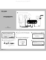
TD-8816
Brand: TP-Link Pages: 2

ADSL2+ Wireless MIMO Router
Brand: Ace Pages: 64

BPTA-CPUMS-V2-SKA
Brand: Bitspower Pages: 6

Pro-C Series
Brand: Hunter Pages: 2

SH-GE90
Brand: Technics Pages: 20


