B&B Electronics Elinx EIRP305-T, User Manual
The B&B Electronics Elinx EIRP305-T is an industrial-grade Ethernet switch, perfect for enhancing network performance. Access its User Manual to explore detailed setup instructions and features. You can download this manual for free from manualshive.com, ensuring you maximize the device’s capabilities efficiently and effectively.
Share
Download


Reviews:
No comments
Related manuals for Elinx EIRP305-T
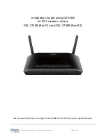
DSL-2740B
Brand: D-Link Pages: 10

TW-200
Brand: TRENDnet Pages: 2

ZoneFlex 7731
Brand: Ruckus Wireless Pages: 56

FieldPoint cFP-RTD-122
Brand: National Instruments Pages: 15

Archer MR500
Brand: TP-Link Pages: 110

IntraCore 6524
Brand: Asante Pages: 150

AR4505GW
Brand: Ozenda Pages: 116

RK-1
Brand: Pakedge Device & Software Pages: 14

ACS express
Brand: Active Communications Pages: 10

DG-BG100
Brand: Digisol Pages: 81

Adam Device
Brand: VideoWave Pages: 12

MC-421
Brand: Modecom Pages: 16

GSW-2416SF
Brand: Planet Pages: 54

ALI-NVR71128R
Brand: ALIBI Pages: 232

Phantom HD
Brand: Net Optics Pages: 2

Horizon D10750
Brand: Ciara Pages: 14

PC-HSICA
Brand: DayTronic Pages: 13

1181413L2
Brand: ADTRAN Pages: 100


