


ELECTRONIC • OLEODYNAMIC • INDUSTRIAL
EQUIPMENTS CONSTRUCTION
Via Parma, 59 – 42028 – POVIGLIO (RE) – ITALY
Tel +39 0522 960050 (r.a.) – Fax +39 0522 960259
E-mail: [email protected] – web: www.zapispa.it
User Manual
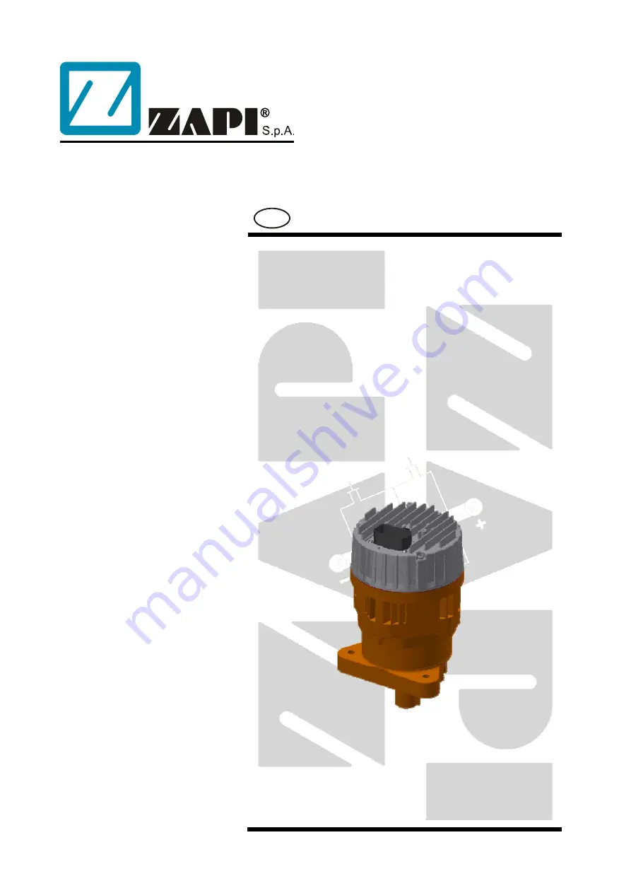
EPS-BLI
HYG
Publication:
AFMNA0AA
Edition:
June 1, 2018
EN


