background image


ELECTRONIC • OLEODYNAMIC • INDUSTRIAL 
EQUIPMENTS CONSTRUCTION 

Via Parma, 59 – 42028 – POVIGLIO (RE) – ITALY 
Tel +39 0522 960050 (r.a.) – Fax +39 0522 960259 
e-mail: [email protected] – web: www.zapispa.it 
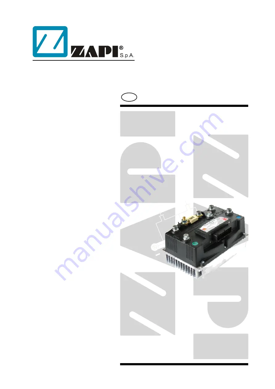


EN


User Manual 


COMBI AC1 


Summary of Contents for COMBI AC1

Page 1: ...ECTRONIC OLEODYNAMIC INDUSTRIAL EQUIPMENTS CONSTRUCTION Via Parma 59 42028 POVIGLIO RE ITALY Tel 39 0522 960050 r a Fax 39 0522 960259 e mail zapi zapispa it web www zapispa it EN User Manual COMBI AC...

Page 2: ...any time and without notice The present publication reflects the characteristics of the product described at the moment of distribution The publication therefore does not reflect any changes in the c...

Page 3: ...ons and possible interferences 13 4 2 4 Wirings I O connections 15 4 2 5 Connection of the encoder 16 4 2 6 Main contactor and key connection 17 4 2 7 Insulation of truck frame 18 4 3 Protection and s...

Page 4: ...MENTS functions list 54 9 5 5 Config menu TESTER functions list 55 10 OTHER FUNCTIONS 57 10 1 Description of console SAVE function 57 10 2 Description of console RESTORE function 58 10 3 Description o...

Page 5: ...COMPANY FUNCTION INIZIALS SIGN GRAPHIC AND LAYOUT FF PROJECT MANAGER FG TECHNICAL ELECTRONIC MANAGER VISA PP SALES MANAGER VISA PN Publication N AEQZP0BA Edition August 2005 AEQZP0BA COMBI AC1 User Ma...

Page 6: ...ontroller for Ac 700W to 3 5Kw AC motors Pump controller for series wounded DC motors up to 7 5 Kw Drivers for ON OFF electrovalves and for one proportional valve electrodistributor Can bus interface...

Page 7: ...8V Inverter maximum current 24V 36V 350A RMS for 2 Inverter maximum current 36V 48V 300A RMS for 2 Inverter operating frequency 8kHz Dc chopper Maximum current 24V 36V 350A for 2 Dc chopper Maximum cu...

Page 8: ...listed here following AMP SAAB version A7 A5 A11 A18 A19 A20 A33 A34 A35 A6 AMP SEAL version A1 A20 A6 A32 A31 A19 A7 A35 A17 A29 It is recommended to connect SAFETY RELATED devices to these double ch...

Page 9: ...onnector On request it is also possible the handling in the Right side of next figure potentiometer in the middle at rest still in combination with a couple of Travel demand switches The Procedure for...

Page 10: ...e The speed transducer is an incremental encoder with two phases shifted at 90 The encoder can be of different types power supply 12V electric output open collector NPN or PNP push pull COMBI AC1 coul...

Page 11: ...e auxiliary circuits use cables 0 5mm section at least For power connections to the motor and to the battery use cables having section of 16 25 mm For the optimum inverter performance the and be as sh...

Page 12: ...mm and rugosity 1 6 m Apply a light layer of thermo conductive grease between the two surfaces to permit better heat dissipation The heat generated by the power block must be dissipated For this to be...

Page 13: ...al time control applications CAN operates at data rate of up to 1 Megabits per second It was invented by the German company Bosch to be used in the car industry to permit communication among the vario...

Page 14: ...ends on the type of nodes modules connected in the The best s network t in terms of power then the preferable If the modules are very differen connection is the daisy chain Module 1 Module 2 Module 3...

Page 15: ...y of today systems needs more and more data signal and information must flow from a node to another CAN is the solution to different problems that arise from this complexity simplified design readily...

Page 16: ...5V 12V positive of encoder power supply A10 GND negative of encoder power supply A8 A phase A of encoder A22 B phase B of encoder AMPSEAL VERSION A25 5V 12V positive of encoder power supply A5 GND ne...

Page 17: ...actor can be carried out following the drawing in the figure AMPSAAB VERSION AMPSEAL VERSION The connection of the battery line switches must be carried out following ZAPI instructions If a mechanical...

Page 18: ...L VERSION 4 2 7 Insulation of truck frame U As stated by EN 1175 Safety of machinery Industrial truck chapter 5 7 there shall be no electrical connection to the truck frame So the truck frame has to b...

Page 19: ...sted to carefully study controller installation and position With few simple shrewdness the degree of controller protection can be strongly increased Protection against uncontrolled movements The main...

Page 20: ...functions 4 4 EMC U EMC and ESD performances of an electronic system are strongly influenced by the installation Special attention must be given to the lengths and the paths of the electric connection...

Page 21: ...the controller with regard to electromagnetic f made by the electronic device There are well defined tests which the machine has to be exposed to These tests are carried out at determined levels of el...

Page 22: ...th ground absorbing excess charge So it is strongly suggested to connect to truck frame all the parts of the truck which can be touched by the operator who is most of the time the source of ESD 4 5 Va...

Page 23: ...ions Modification of parameters through the programming console Internal hour meter with values that can be displayed on the console Memory of the last five alarms with relative hour meter and tempera...

Page 24: ...6 DESCRIPTION OF THE CONNECTORS 6 1 Connectors of the logic AmpSaab version 1 14 15 28 29 42 Page 24 86 AEQZP0BA COMBI AC1 User Manual...

Page 25: ...o the Hard Soft microswitch active high A7 TILLER Tiller microswitch input active high VB A8 ENC A Traction motor encoder phase A A9 PENC Encoder Positive Supply 5 or 12Vdc A10 NENC Negative of the En...

Page 26: ...s active high VB A34 IN7 Input of the switch DIGITAL INPUT 7 A35 IN8 Input of the switch DIGITAL INPUT 8 A36 LIFT SW Lift request switch input active high VB A37 LIFTING CUTOUT Lift stop input Active...

Page 27: ...Negative serial reception pin A22 THMOT Traction motor thermal sensor input The internal pull up is a fixed 2mA Max 5V source current A23 NEV6 Output of the electrovalve 6 driver driving to Batt A24 N...

Page 28: ...P B B Negative of the battery B Positive of the battery BF Positive of the battery before the fuse P Output of the Pump Motor U V W Connection bars of the three motor phases follow this sequence and...

Page 29: ...7 DRAWINGS 7 1 Mechanical drawing AEQZP0BA COMBI AC1 User Manual Page 29 86...

Page 30: ...7 2 Connection drawing 7 2 1 AmpSaab version Page 30 86 AEQZP0BA COMBI AC1 User Manual...

Page 31: ...7 2 2 AmpSeal version AEQZP0BA COMBI AC1 User Manual Page 31 86...

Page 32: ...ding on a jumper inside the controller Step5 Connect the plus battery voltage through a key switch at the KEY input CNA 13 CNA 10 in AmpSeal This is the input for the controller supply Step6 Connect t...

Page 33: ...the machine Test the parameters in both directions Step7 Set the FREQUENCY CREEP level starting from 0 6 Hz The machine should just move when the accelerator microswitch is closed Increase the Level...

Page 34: ...Step15 Make the choice for the truck behaviour on a slope If the Stop on ramp option is ON set the desired value of auxiliary time parameter Page 34 86 AEQZP0BA COMBI AC1 User Manual...

Page 35: ...Description of console hand set connection Digital consoles used to communicate with AC inverter controllers must be fitted with EPROM CK ULTRA minimum Release Number 3 02 The section describes the Za...

Page 36: ...9 3 Description of the console menu 9 3 1 Master AmpSaab version Page 36 86 AEQZP0BA COMBI AC1 User Manual...

Page 37: ...9 3 2 Master AmpSeal version AEQZP0BA COMBI AC1 User Manual Page 37 86...

Page 38: ...9 3 3 Slave AmpSaab version Page 38 86 AEQZP0BA COMBI AC1 User Manual...

Page 39: ...9 3 4 Slave AmpSeal version AEQZP0BA COMBI AC1 User Manual Page 39 86...

Page 40: ...Display will show SET OPTIONS CONFIG MENU SET OPTIONS Press ENTER to go in the SET OPTIONS MENU The Display will show the first OPTION HOURCOUNTER RUNNING Press SET UP or SET DOWN button in order to m...

Page 41: ...rm is raised when the battery level is calculated being less than or equal to 10 of the full charge The BATTERY LOW alarm inhibits the Lifting function 4 STOP ON RAMP Only when the encoder is present...

Page 42: ...et OFF the Quick Inversion switch is Normally Open function active when switch closes 9 4 2 Config menu ADJUSTMENTS functions list To enter the CONFIG MENU it is necessary to push in the same time the...

Page 43: ...is parameter together with the THROTTLE X POINT changes the characteristic of the accelerator input curve see also paragraph 13 5 when the accelerator is de pressed to X point per cent the correspondi...

Page 44: ...2B ZAPI 0 00 24V 350A 00000 2 Press ENTER to go into the General Menu 3 The Display will show PARAMETER CHANGE MAIN MENU PARAMETER CHANGE 4 Press ENTER to go into the Parameter Change menu 5 The Displ...

Page 45: ...ely released The parameter sets the time needed to decelerate the traction motor from 100Hz to 0Hz 6 SPEED LIMIT BRK Seconds It controls the deceleration ramp when a speed reduction has been activated...

Page 46: ...the speed percentage of the maximum speed in the inching mode 17 INCHING TIME When the inching mode is active for a period of time higher then this value the truck automatically stops and the operator...

Page 47: ...X From 0 to 100 resolution of 1 INCHING SPEED Max Sp From 0 to 100 resolution of 1 INCHING TIME Sec From 0 to 10 sec resolution of 0 1 STOP SMOOTH Hz From 3 to 20 Hz resolution of 1Hz STOP BRAKE SMOOT...

Page 48: ...plied to the motor expressed in per cent of the actual battery voltage Note when DC_LINK COMPENSATION is set ON the VOLTAGE BOOSTER reading will not match perfectly the booster setting because this la...

Page 49: ...iller ON VB When it is closed to a battery key voltage the H S request is Active OFF GND When it is not connected to a battery key voltage or it is connected to GND the H S request is not active 14 DE...

Page 50: ...When it is not closed to a battery key voltage or connected to GND the voltage the digital input 7 request is not active 21 IN 8 SWITCH Only for AmpSaab version ON OFF This is the level of the digital...

Page 51: ...controlled Digital the related output manages an on off valve 3 EV1 TYPE Analog digital defines the type of the EV1 electrovalve voltage controlled Analog the related output manages a proportional val...

Page 52: ...Set the deceleration ramp for the pump motor 4 SPEED LIMIT Percentage It limits the maximum speed of the lifting function Percentage of the maximum voltage applied to the pump motor 5 CREEP SPEED Perc...

Page 53: ...lectrovalve when related output is set as Analog refer to Set Option menu 15 EV1 CLOSE DELAY In seconds It defines the closing ramp of the evp1 electrovalve when related output is set as Analog refer...

Page 54: ...This is the Gain of the Pump chopper Current Sensing Amplifier NOTE only Zapi technicians should change this value 2 SET CURRENT set the current limit for the measurement in the TESTER menu 3 AUX OUTP...

Page 55: ...MPERATURE C Measure of the pump motor temperature 7 LIFTING CONTROL Volt Measure of the lift lower potentiometer input signal CPOTLIFT CNA 25 in AmpSaab connector CNA 30 in AmpSeal connector 8 HANDLE...

Page 56: ...S switch CNA 6 in AmpSaab CNA 29 in AmpSeal 18 DIGITAL INPUT 13 On off it determines if the input 13 is active or not Horn switch CNA 21 in AmpSaab 19 SET POINT EVP This parameter shows the setpoint...

Page 57: ...pening Zapi Display CA1S2B ZAPI V0 0 24V 350A 00000 Press ENTER to go into the General menu The Display will show MAIN MENU PARAMETER CHANGE Press ROLL UP or ROLL DOWN button until SAVE PARAM appears...

Page 58: ...oller memory will be written over and replaced with data being restored Flow Chart showing how to use the RESTORE function of the Digital Console Opening Zapi Display CA1S2B ZAPI V0 0 24V 350A 00000 P...

Page 59: ...lly relating to the minimum level The two graphs show the output voltage from a non calibrated potentiometer with respect to the mechanical zero of the control lever MI and MA indicate the point where...

Page 60: ...SETTING 4 8 4 8 Press ENTER to clear these values Display will show 0 0 Select Forward Direction close any interlock switches that may be in the system MIN VACC MAX 0 0 0 0 Slowly depress the acceler...

Page 61: ...an this percentage of the MAX VACC setting This adjustment define the width of a dead zone close to the neutral position THROTTLE X POINT THROTTLE Y POINT the speed of the truck grows up with a fixed...

Page 62: ...t Max Adj and the Bat Min Adj It is possible to adapt the Battery Charge Detection to your specific battery by changing the above two settings e g if the Battery Discharged Detection occurs when the b...

Page 63: ...t is compared with a threshold value function of the actual charge percentage in a table and with comparison is found a new charge percentage 4 Thresholds value can be changed with parameters Bat Max...

Page 64: ...to the first time the alarm occurred In this way comparing this hourmeter with the controller hourmeter it is possible to determine When this alarm occurred the first time How many hours are elapsed...

Page 65: ...Lc opened Eb applied start up Valve or pump or traction request Logic Failure 1 Waiting for trac Overvoltage Undervoltage condition has been detected Valve pump traction stopped Lc opened Eb applied...

Page 66: ...ontroller internal charging resistance is damaged C The charging circuit has a failure inside the controller D There is a problem in the controller power section 2 VMN LOW Cause 1 start up test Before...

Page 67: ...ED Cause Before switching the LC on the software checks the power bridge it turns on alternatingly the Low side and High side Power Mosfets and expects the phases voltage to decrease down to BATT incr...

Page 68: ...tactor is stuck The controller drives the bridge for some tens milliseconds trying to discharge the capacitors bank If they don t discharge the fault condition is entered Troubleshooting It is suggest...

Page 69: ...undervoltage or a overvoltage condition A If the alarm happens during traction acceleration or driving hydraulic functions it is very likely it is an undervoltage condition check battery charge condi...

Page 70: ...k both the electric and the mechanical encoder functionality the wires crimping B Check the encoder mechanical installation if the encoder slips inside its compartment raising this alarm condition C A...

Page 71: ...t of the controller which must be replaced 25 WRONG SETPOINT Cause This is a safety related test The Master C has detected a Slave C wrong hydraulic function setpoint Troubleshooting This is a interna...

Page 72: ...tected in eeprom or in eeprom management Controller works using Deafult parameters continuous Motor temperature Motor temperature sensor is opened if digital or has overtaken the threshold of 150 C if...

Page 73: ...ting sequence Troubleshooting The possible reasons for this alarm are use the readings in the TESTER to facilitate the troubleshooting A A travel demand active at key on B Presence man sensor active a...

Page 74: ...al Switch the key off and on to check the result If the alarm occurs permanently it is necessary to replace the controller If the alarm disappears the previously stored parameters will have been repla...

Page 75: ...de Troubleshooting Check the voltage on NPOT and the potentiometer connections 14 TILLER OPEN Cause Warning when the tiller is released after a fixed period of time of standby 30 seconds the main cont...

Page 76: ...or traction request Safety Feed TG Waiting for Node Slave uC has detected a problem on the feedback of Lc driver valve pump traction stopped Lc opened Eb applied continuous Key re cycle Safety Feed E...

Page 77: ...ions If motor windings cables have leakages towards truck frame That the LC power contact closer properly with a good contact If no problem are found on the motors the problem is inside the controller...

Page 78: ...s due to overvoltage condition check line contactor contact battery power cable connection 6 WRONG ZERO Cause The outputs of the amplifiers used to measure the motor currents and voltage are checked t...

Page 79: ...bus malfunctioning which blinds master slave communication Otherwise it is an internal fault of the controller which must be replaced 13 NO CAN MESSAGE 2 Cause No Can messages from the master microcon...

Page 80: ...current feedback is always 0A even when pump motor is running Pump motor stopped pump function pump request motor temperature Pump Warning Pump motor temperature high Pump chopper maximum current red...

Page 81: ...ives the outputs the problem is located in the harness and in the coils 4 VALVE DRIVER SHORTED Cause One or more on off valve drivers are shorted Troubleshooting Check if there is a short or a low imp...

Page 82: ...ondition as a consequence the pump controller itself cannot enter an operative status but has to WAIT for the Master controller coming out from the fault condition 11 INCORRECT START Cause This is a w...

Page 83: ...PROM operation refer to Console manual Switch the key off and on to check the result If the alarm occurs permanently it is necessary to replace the controller If the alarm disappears the previously st...

Page 84: ...19 REDUCTION BY MASTER Cause The master has requested a reduction of performance of the slave Troubleshooting Check in the master the cause of the reduction Page 84 86 AEQZP0BA COMBI AC1 User Manual...

Page 85: ...SPARE PARTS Part number Description C16506 FUSE PROT 425A INTERAS60 for 24v and 48v version C12505 AMPSAAB CONNECTOR 42 pins Female C12532 AMPSEAL CONNECTOR 35 pins Female AEQZP0BA COMBI AC1 User Man...

Page 86: ...e mechanical operation of the pedal or tiller Are the return springs ok Do the potentiometers wind up to their full or programmed level Check every 3 months Check the mechanical operation of the Conta...

Reviews: