background image

INSTALL., OPER., MAINT.

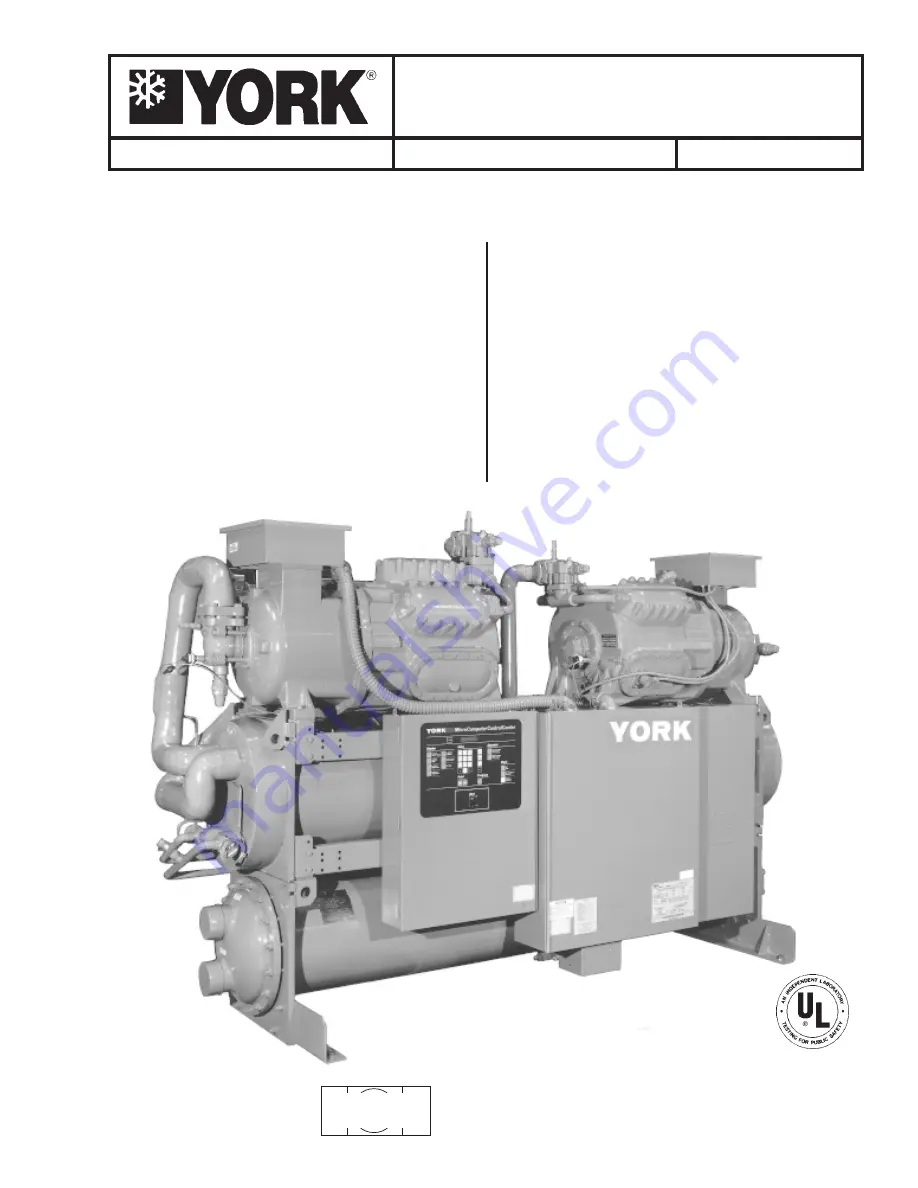
RecipPak LIQUID CHILLERS

WATER COOLED - RECIPROCATING HERMETIC

Supersedes:  150.24-NM27 (1295)

Form 150.24-NM27 (298)

MODELS

200, 230, 460-3-60

60 HZ

YCWJ45EE0, YCRJ45E00,

YCWJ55HE0, YCRJ55H00,

YCWJ56HF0, YCRJ56H00,

YCWJ66KH0, YCRJ66K00,

YCWJ67KH0, YCRJ67K00,

YCWJ77KH0, YCRJ77K00,

YCWJ88MH0, YCRJ88M00

YCWJ99MJ0, YCRJ99M00

STYLE “A”*

50 HZ

YCWJ56EE0, YCRJ56E00,

YCWJ66HE0, YCRJ66H00,

YCWJ67HF0, YCRJ67H00,

YCWJ77KH0, YCRJ77K00,

YCWJ78KH0, YCRJ78K00,

YCWJ88KH0, YCRJ88K00,

YCWJ99MH0, YCRJ99M00

STYLE “A”*

26214A

*With EPROM

    (Standard, Brine & Metric Models, Combined)

031-01652-001

or

031-01096-001

Summary of Contents for YCWJ45EE0

Page 1: ...5HE0 YCRJ55H00 YCWJ56HF0 YCRJ56H00 YCWJ66KH0 YCRJ66K00 YCWJ67KH0 YCRJ67K00 YCWJ77KH0 YCRJ77K00 YCWJ88MH0 YCRJ88M00 YCWJ99MJ0 YCRJ99M00 STYLE A 50 HZ YCWJ56EE0 YCRJ56E00 YCWJ66HE0 YCRJ66H00 YCWJ67HF0 Y...

Page 2: ...9 MOUNTING DETAIL FOR SPRING ISOLATORS 9 CONTROL PANEL 9 WATER COOLED 10 REMOTE CONDENSER 11 ELECTRICAL DATA 12 INSTALLATION 18 WIRING DIAGRAM 27 UNIT CONTROLS AND OPERATION 38 COMPRESSOR CAPACITY CON...

Page 3: ...R NOMENCLATURE J MODELS UNIT NOMENCLATURE The model number denotes the following characteristics of the unit Y C W J 6 7 H F 0 46 P A YORK S Special Blank if not used Chiller Design Level W Water Cool...

Page 4: ...R COOLER INLET LIQUIDSTOP VALVE LIQUID SOLENOID VALVES FILTERDRIERS LIQUID STOP VALVE CONDENSER 1 2 RELIEF VALVE COOLER OUTLET COOLER 26125A REAR VIEW OPTIONALSINGLE POINTPOWER CONNECTION POWERPANEL C...

Page 5: ...8 CYLINDER MODEL J G COMPRESSOR DISCHARGE STOP VALVE SUCTIONPRESSURE CONNECTION CAPACITY CONTROL SOLENOIDS RAINTIGHT TERMINALBOX SUCTION STOP VALVE SIGHT GLASSES 2 OILCHARGING VALVE CRANKCASE HEATER...

Page 6: ...Oll Temperature Max 1 160 F Maximum Sat Discharge Temp 2 150 F Maximum Ambient 115 F Minimum Ambient 40 F Minimum Leaving Liquid Temp 3 40 F Maximum Leaving Liquid Temp 50 F YCWJ YCRJ Models YCWJ 60...

Page 7: ...CAUTION Excessive flow will cause damage to the cooler Do not exceed max cooler GPM Special care should be taken when multiple chillers are fed by a single pump FIG 2 COOLER WATER PRESSURE DROP PRESSU...

Page 8: ...60HP YCRJ 50 HZ SYS 1 G44 P 67HP G63 Q 75HP G63 Q 75HP G64 S 96HP G64 S 96HP G83 T 113HP G83 T 113HP SYS 2 G63 Q 75HP G63 Q 75HP G64 S 96HP G64 S 96HP G83 T 113HP G83 T 113HP G83 T 113HP UNIT 60 HZ 5...

Page 9: ...1600 1600 1600 1600 6 000 6 400 Isolator AWCB 1600 YCWJ55H00 60 1625 1625 1625 1625 5 950 6 500 Isolator AWCB 1625 YCWJ56H00 60 1650 1650 1650 1650 6 100 6 600 Isolator AWCB 1625 YCWJ66K00 60 1688 168...

Page 10: ...MODEL 60HZ A B C D E F G H J K L M N P YCWJ45EE0 10 0 3 8 6 1 7 16 2 11 2 9 1 8 4 7 3 16 8 1 4 8 1 4 3 6 1 2 7 5 8 1 7 3 4 1 3 1 2 5 6 4 11 11 16 YCWJ55HE0 10 0 3 8 6 3 7 16 2 11 2 10 1 8 4 7 3 16 8...

Page 11: ...1 8 3 1 8 2 5 8 1 5 8 2 4 2 5 8 3 6 1 2 1 5 1 2 2 1 2 3 5 1 2 YCRJ88M00 1 8 7 8 3 2 3 4 8 3 1 8 1 5 8 3 0 3 1 8 3 6 1 2 1 5 1 2 2 2 1 2 3 5 1 2 YCRJ99M00 1 8 7 8 3 2 3 4 8 3 1 8 1 5 8 3 0 3 1 8 3 6 1...

Page 12: ...412 56HF0 17 200 3 60 251 300 450 400 2 4 250MCM 450 200 731 56HF0 28 230 3 60 226 300 400 400 2 4 250MCM 400 180 636 56HF0 40 380 3 60 132 175 225 200 2 4 250MCM 225 105 385 56HF0 46 460 3 60 113 15...

Page 13: ...800 375 1101 408 500 700 400 2 4 250MCM 700 326 976 241 300 400 400 2 4 250MCM 400 192 591 204 250 350 200 2 4 250MCM 350 163 488 236 300 400 400 2 4 250MCM 400 188 760 159 200 250 200 2 4 250MCM 250...

Page 14: ...3 60 301 400 500 400 2 4 250MCM 500 240 826 66K00 40 380 3 60 174 225 300 200 2 4 250MCM 300 139 467 66K00 46 460 3 60 151 200 250 200 2 4 250MCM 250 120 413 77K00 50 380 415 3 50 177 225 300 200 2 4...

Page 15: ...0 400 2 4 250MCM 600 276 950 301 400 500 400 2 4 250MCM 500 240 826 174 225 300 200 2 4 250MCM 300 139 467 151 200 250 200 2 4 250MCM 250 120 413 177 225 300 200 2 4 250MCM 300 141 585 116 150 200 200...

Page 16: ...60 271 300 350 400 350 1 6 350MCM 1 1 600MCM OR 2 1 250MCM 66KH0 46 460 3 60 232 300 300 400 300 1 6 350MCM 1 1 600MCM OR 2 1 250MCM 77KH0 50 380 415 3 50 268 300 350 400 350 1 6 350MCM 1 1 600MCM OR...

Page 17: ...350MCM 66K00 28 230 3 60 541 600 700 600 700 1 3 6 350MCM 1 4 1 0 350MCM 66K00 40 380 3 60 313 350 450 400 450 1 3 6 350MCM 1 2 4 0 500MCM 66K00 46 460 3 60 271 300 350 400 350 1 6 350MCM 1 1 600MCM...

Page 18: ...n page 6 The following paragraphs outline procedures to be fol lowed INSPECTION As soon as it is received the unit should be inspected for any damage done in transit If damage is evident it should be...

Page 19: ...or mounting bracket underneath the unit base It will be necessary to raise the unit to do this Note that the bolt should be inserted from the bottom of the mounting bracket FIG 4 FOUNDATIONS The isola...

Page 20: ...mini mum leaving water temperature of 65 F The regulator should be installed in the entering water line however the outlet piping leaving the condenser should contain a vertical rise approximately 3 h...

Page 21: ...gement provides a liquid column which raises the pressure of the refrigerant above the saturation pressure and thus assures proper subcooling at the expansion valve 7 The condenser must provide liquid...

Page 22: ...echanical Engineers United Engineer ing Center 345 East 47th Street New York NY 10017 Since YCR chillers are shipped containing Refriger ant 22 as a holding charge the compressor discharge valve and t...

Page 23: ...in the discharge line as close to the unit as possible They can be mounted vertically or horizontally but should never be installed in a riser One side of the muffler is stamped TOP for horizontal mo...

Page 24: ...d be noted that under unusual circumstances a possibility exists for freezing water inside the system Such moisture or free water may be removed by the Double Evacuation procedure as explained in Para...

Page 25: ...nnected to the sys tem charging port in the refrigerant liquid stop valve Allow the dry nitrogen to flow into the system until the pressure reaches zero pound or slightly above Stop the dry nitrogen f...

Page 26: ...n However if it is undesirable it is the responsibility of the installer to make provisions to field insulate the com pressor or install a factory insulation kit when they be come available Contact YO...

Page 27: ...FORM 150 24 NM27 YORK INTERNATIONAL 27 FIG 8 ELEMENTARY DIAGRAM WIRING DIAGRAM With or Without I O Expansion Board...

Page 28: ...tor auxiliary contacts must be suppressed with YORK P N 031 00808 000 sup pressor across the relay contactor coil Any contacts connected to flow switch inputs or BAS inputs on terminals 13 19 of TB3 o...

Page 29: ...FORM 150 24 NM27 YORK INTERNATIONAL 29 CONTROL CIRCUIT With I O Expansion Board LD02106...

Page 30: ...30 YORK INTERNATIONAL FIG 9 SYSTEM WIRING...

Page 31: ...FORM 150 24 NM27 YORK INTERNATIONAL 31 LD02678...

Page 32: ...32 YORK INTERNATIONAL FIG 9 SYSTEM WIRING Cont d LD02110 MOTOR TERMINAL BOX WIRING WITH MODEL 15AA MOTOR PROTECTOR...

Page 33: ...FORM 150 24 NM27 YORK INTERNATIONAL 33 LD02357 MOTOR TERMINAL BOX WIRING WITH MODEL 31AA MOTOR PROTECTOR...

Page 34: ...34 YORK INTERNATIONAL FIG 10 CONNECTION DIAGRAM LD02358 MICROPANEL CONNECTION DIAGRAM WITHOUT EXPANSION BOARD...

Page 35: ...FORM 150 24 NM27 YORK INTERNATIONAL 35 LD02679...

Page 36: ...36 YORK INTERNATIONAL MICROPANEL CONNECTION DIAGRAM With I O Expansion Board LD02107...

Page 37: ...FORM 150 24 NM27 YORK INTERNATIONAL 37 LD02108...

Page 38: ...ping and loading unloading de cisions are performed by the Microprocessor to main tain leaving water temperatures These decisions are a function of temperature deviation from setpoint and rate of chan...

Page 39: ...ential I O EXPANSION BOARD Introduced in the latter part of 1997 the I O Expansion Board allows the Micro to receive additional analog in puts from Oil Temperature Sensors and optional Dis charge Temp...

Page 40: ...216A MICROPROCESSOR BOARD 2TTRANSFORMER RELAY OUTPUT BOARD 1 TB3 CONNECTIONS FOR FLOW SWITCH LEAD LAG SELECTERAND EMS BAS CONTROLS LOCATION OF OPTIONAL RELAY OUTPUT BOARD 2 POWERSUPPLY BOARD 28697A PO...

Page 41: ...g potential future problems troubleshooting and commissioning the chiller Displayed data will be real time data displayed on a 40 character display consisting of 2 lines of 20 characters The display w...

Page 42: ...en selected by the user These options are se lected by the S1 Dip Switch on the Microprocessor Board Fig 15 Proper programming of the switch is important during commissioning of the chiller The OPTION...

Page 43: ...D I S C H A R G E P R E S S U R E F A N C O N T R O L M A N U A L L E A D L A G A U T O M A T I C L E A D L A G S T A N D A R D C O N D E N S E R F A N C O N T R O L S H A R E D C O N D E N S E R F A...

Page 44: ...will be from leaving water temperature SWITCH 5 OPEN Display messages will show units of measure in English units F PSI etc CLOSED Display messages will show units of measure in Metric units C kPa et...

Page 45: ...ign ment is made whenever both compressors shut down The micro will then assign the lead to the compressor with the shortest anti recycle time SWITCH 8 OPEN Switch 8 positioning on YCW YCR water coole...

Page 46: ...e STATUS key will enable the operator to determine current chiller operating status as a whole and as individual systems The messages displayed will in clude running status cooling demand fault status...

Page 47: ...g total loss of cooling When this message appears discharge pres sure has exceeded the user programmable threshold and the micro is unloading the affected system to prevent shutdown on a manual high p...

Page 48: ...I G H A M B I E N T T E M P S Y S 1 L O W O I L P R E S S C H I L L E R F A U L T 1 1 5 V A C U N D E R V O L T A G E S Y S 2 L O W O I L P R E S S S Y S 1 L O W S U C T I O N S Y S 2 L O W S U C T I...

Page 49: ...L E R F A U L T 1 1 5 V A C U N D E R V O L T A G E S Y S 1 H I G H O I L T E M P S Y S 2 H I G H O I L T E M P S Y S 1 L O W S U C T I O N S Y S 2 L O W S U C T I O N S Y S 1 O I L T E M P I N H I B...

Page 50: ...ough available data after any one of the following keys is pressed PROGRAM SET SCHEDULE HOLIDAY OPER DATA HISTORY Cancel Key The CANCEL key allows the user to change errors in the data being programme...

Page 51: ...ST BE CHECKED AND PROPERLY PRO GRAMMED WHEN COMMISSIONING THE CHILLER FAILURE TO PROPERLY PROGRAM THESE VALUES MAY CAUSE DAMAGE TO THE CHILLER OR OPERA TION PROBLEMS DISCHARGE CUT OUT The DISCHARGE CU...

Page 52: ...he absolute maximum temperature capability of the electro mechanical components To program the OUTSIDE AIR TMP HIGH CUT OUT key in the desired value and press the ENTER key The new value will be enter...

Page 53: ...0 Example 085 PSIG RATE CONTROL TEMP The RATE CONTROL TEMP establishes a temperature range over which the micro may override normal system loading timers and react to actual rate of change of re turn...

Page 54: ...is adjustable from44 70PSIG IntheBRINE PROCESSMODE SW1 CLOSED the cut out is adjustable from 20 70 PSIG RATE SENSITIVITY The RATE SENSITIVITY establishes the rate of change of return or leaving water...

Page 55: ...nd date will be dis played when the SET TIME key is pressed CLOCK KEYS PROGRAMMING THE SYSTEM CLOCK AND DAILY START STOP SCHEDULE To program the day time and date first press the AD VANCE DAY key unti...

Page 56: ...ONDAY that the ENTER KEY is not pressed changing times programmed for the rest of the week If the chiller is not cycled by the DAILY SCHEDULE but is required to run whenever the system switches are on...

Page 57: ...ignored and the chiller will start up when water temperature allows unit switch permits and system switches permit Normally this key is not used unless an emergency forces the chiller to require oper...

Page 58: ...according to the user s application and Switch 4 of Dip Switch S1 on the Micro Board is properly configured to select Return or Leaving control the chilled liquid setpoints can then be programmed into...

Page 59: ...well above or well below the desired setpoint will result To program the Chilled Liquid Setpoints press the CHILLED LIQUID TEMP RANGE key The display will first exhibit a message that RETURN WATER TE...

Page 60: ...ble limit The micro will accept a range of programmable values between 0 1 20 F NOTE When programming values between 0 1 9 9 F it is required to first key in a 0 or 00 Ex ample 05 9 F Loading may be i...

Page 61: ...press the ENTER key The new value will be entered into memory and the display will advance to the next user programmable limit The micro will accept a range of programmable values between 0 5 5 0 F mi...

Page 62: ...display will continue to show the LWT and Control Range message until another key is pressed CAUTION Too small of a CR selection will cause com pressor loader cycling If compressor cycling occurs leav...

Page 63: ...RATURE CONTROL ABOVE THE RATE CONTROL TEMPRANGE h RATECONTROLTEMPRANGE RATE CONTROL TEMP 10 F i h CONTROLRANGE CR 44 46 F i BELOWTHE CONTROLRANGE 56 46 45 44 or initiate unloading if temperature drops...

Page 64: ...ad a stage 2 F below the tempera ture at which it was loaded assuming unloading tim ers and rate control software allows The RATE SENSITIVITY is a means of overriding the loading unloading timers when...

Page 65: ...stan dard chillers may appear delayed time between stages increased when miss ing steps are activated or deactivated by the micro NOTE 1 The Lead Comp 2 Steps Lag Comp Off Step is skipped on a tempera...

Page 66: ...NTROL RANGE between the TAR GET and LOW LIMIT WATER TEMPERATURE As men tioned earlier in this manual the CONTROL RANGE is the temperature range of leaving water temperature that is acceptable to the u...

Page 67: ..._ _ _ _ _ _ _ _ _ _ _ _ _ _ _ _ _ _ _ _ _ _ _ _ _ 4 LEAD COMP 1 STEP LAG COMP UNLOADED _ _ _ LEAD COMP 1 STEP LAG COMP UNLOADED 3 LEAD COMP UNLOADED LAG COMP UNLOADED _ _ _ LEAD COMP UNLOADED LAG COMP...

Page 68: ...sor starts If after 4 seconds the motor current drops below 15 FLA the micro will shut the compressor down NOTE Do not confuse FLA and RLA FLA full load amps is approximately 1 2 x RLA RLA run ning lo...

Page 69: ...e pressure transducers are installed Oil Pressure Safety The Oil Pressure Safety assures that the compressor s mechanical components receive proper lubrication The micro begins monitoring compressor o...

Page 70: ...pproximately 1 2 x RLA RLA run ning load amps specified on the motor name plate is typical current demand under rated op erating conditions in a fully loaded system There fore do not expect to see 100...

Page 71: ...cycle timer elapses This is the same anti recycle timer which is AUTOMATIC RESET SAFETIES An Automatic Reset Safety will shut the entire chiller down on a fault when the safety threshold is exceeded a...

Page 72: ...ut out On water cooled chillers this safety reduces the chance of tripping the relief valve due to a very high rate of rise in pressureresultingfromacontrolsproblemwhichwouldcause condenser water flow...

Page 73: ...tart the system will cease to pump down Pumpdowns will begin again after a cooling start occurs This is to pre vent oil loss in the system However if one system reaches 120 pumpdowns while the other s...

Page 74: ...be temporarily stored in mem ory and transmission of this data will begin to the re mote printer As the data is transmitted it will be erased from memory A sample printout is shown in Fig 23 PRINT KE...

Page 75: ...DISCHARGEPRESSURE 143 PSIG OILPRESSURE 75 PSID LIQUIDLINESOLENOID ON RUNPERMISSIVE ON STAGESOFLOADING 1 FORWARDFANS 2 REVERSEFANS OFF HOTGASBYPASSVALVE OFF SYSTEM2DATA COMPRESSORSTATUS ON MOTORAMPS 0...

Page 76: ...e offered NOTE Some of the information that may be recovered i e fan operation discharge pressures stages of loading etc may not apply to the chiller The micro is capable of operating these items and...

Page 77: ...last start is displayed This message provides a real time display of the time left on the Load Timer The Load Timer is a constantly recycling timer that the micro utilizes in conjunction with rate con...

Page 78: ...water pump to close History The HISTORY key also allows the user to scroll through the SAFETY SHUTDOWN buffers to display information relating to the last 3 Safety Shutdowns which occurred Information...

Page 79: ...lay shows the suction pressure of SYS 1 at the time of the fault This message indicates SYS 1 discharge pressure at the time of the fault This display will be a fixed value unless the Discharge Pressu...

Page 80: ...SYS 2 liquid line solenoid was energized ON or de energized OFF at the time of the fault This message informs the operator if SYS 2 Run Per missive flow switch remote START STOP was in the RUN mode ON...

Page 81: ...control panel The dry con tacts are normally open N O and will close when con trol power is applied to the panel if no fault conditions are present If power is not lost or a fault lockout occurs the c...

Page 82: ...kly 4 If the lead compressor is locked out faulted and waiting to restart SYS switch on the micro board is off or a run permissive is keeping an individual sys tem from running the lag compressor is s...

Page 83: ...s is shown in Fig 27 MEMORY BATTERY BACK UP The Microprocessor board contains a Real Time Clock RTC I C Chip with an internal battery back up The bat tery back up assures that any programmed values cl...

Page 84: ...DING Pulldown demand limit ing and REMOTE SETPOINT RESET These functions can be easily utilized by connecting user supplied dry contacts to the terminals on the TB3 Terminal Block REMOTE START STOP BY...

Page 85: ...ts minimum step of capacity which places the entire system at minimum possible capacity To shut down the lag compressor a dry contact should be connected between terminals 13 16 See Fig 14 for the loc...

Page 86: ...the chilled water pump NOTE Any inductive devices contactor relay coil con nected to these contacts must be suppressed with YORK P N 031 00808 supplied by others Otherwise nuisance faults may occur CH...

Page 87: ...al wires metal chips etc 8 Visually inspect wiring power control Must meet NEC and all local codes See Fig 12 14 9 Check for proper size fuses in main and control power circuits 10 Verify that field w...

Page 88: ...CE for unit operation The compressor will start and a flow of liquid should be noted in the liquid indicator After several min utes of operation the bubbles will disappear and there will be a solid co...

Page 89: ...o the piping Example LIQUID LINE PRESSURE 202 PSIG converted to 102 F Minus Liquid Line Temperature 90 F Subcooling 12 F Record SYS 1 _______ SYS 2 _______ The proper refrigerant charge is attained wh...

Page 90: ...mpressor will load its 2nd step of loading if cooling demand requires temperature and rate control The lag com pressor remains unchanged at the 1st step of load ing 15 After 7 minutes of run time the...

Page 91: ...essor will unload two steps to its 1st step of 3 loading steps 12 After 10 minutes and 4 seconds of run time the motor current of the lag compressor must be 14 FLA and 115 FLA Oil pressure must be 5 P...

Page 92: ...e If it is necessary to charge oil refer to item 3 under the ANNUAL MAINTENANCE section 3 Check the refrigerant circuit for leaks 4 Operating Pressures and Temperatures Check to see that operating pre...

Page 93: ...nk case to the proper level It is necessary that the suc tion end of the hand oil pump be kept submerged under the oil level in the container at all times to avoid entrance of air into the compressor...

Page 94: ...oprocessor in both return and in leaving water control LWT Control Hot Gas Operation The hot gas solenoid is energized when the leaving wa ter temperature falls below the Target water temperature if t...

Page 95: ...001 YCRJ55H0 375 05886 001 YCRJ56H0 375 05886 001 YCRJ66H0 375 05886 001 YCRJ67K0 375 05886 002 YCRJ77K0 375 05886 002 YCRJ88M0 375 05886 003 YCRJ99M0 375 05886 004 In addition a 471 01232 101 kit mus...

Page 96: ...d is 25 feet Twisted pair shielded cable is required 3 The printer must be supplied a 115 VAC source 4 The printer may be left connected to the micro panel YORK INTERNATIONAL CORPORATION RECIPROCATING...

Page 97: ...e as shown on the Micro Logic Board Do not connect at the printer end of the cable Printer Configuration 2 Switches on the printer must be properly configured Remove the paper roll to access these swi...

Page 98: ...ng the RE MOTE RESET TEMP RANGE Key on the Keypad All refresh requirements normally asssociated with PWM inputs will be automatically taken care of by the elec tronics in the option It is important to...

Page 99: ...e REMOTE RESET TEMP SETPOINT RANGE page 84 for 40 F which will allow the R11 pot to be adjusted for an offset of as much as 20 F when the contact is closed The dry contact should be connected directly...

Page 100: ...gize 2 External motor protector tripped 2 Check for defective External motor protector wiring and motor problems Assure that motor protector is not tripped due to external high pressure switch 3 Defec...

Page 101: ...ce transducer 7 Fouled compressor suction strainer 7 Remove and clean strainer 8 Faulty wiring to transducer 8 Check wiring High Dsch Fault 1 Cooling tower operational problems 1 Check fans fuses and...

Page 102: ...in 33 0 F 2 09 waterpiping 36 0 F 2 22 38 0 F 2 28 41 0 F 2 37 43 0 F 2 43 46 0 F 2 54 48 0 F 2 60 50 0 F 2 67 53 0 F 2 77 55 0 F 2 83 57 0 F 2 89 59 0 F 2 95 61 0 F 3 02 63 0 F 3 08 65 0 F 3 14 67 0...

Page 103: ...d 3 Demand not great enough 3 OK Become familiar with control operation 4 Defective loading solenoid 4 Replace compressor loading solenoid 5 Faulty wiring to loading solenoid 5 Check wiring 6 Defectiv...

Page 104: ...03 217 4 40 0 104 219 2 40 6 105 221 0 41 1 106 222 8 41 7 107 224 6 42 2 108 226 4 42 8 109 228 2 43 3 110 230 0 43 9 111 231 8 44 4 112 233 6 45 0 113 235 4 45 6 114 237 2 46 1 115 239 0 46 7 116 24...

Reviews: