YOKOGAWA vigilantplant uR20000 Series, Operation Manual
The YOKOGAWA VigilantPlant uR20000 Series is a cutting-edge industrial automation system. Unlock the true potential of your operations with this versatile and reliable product. Enhance efficiency and ensure seamless workflows by accessing its comprehensive operation manual available for free download at manualshive.com.
Share
Download


Reviews:
No comments
Related manuals for vigilantplant uR20000 Series

POVCAM AG-MDR25E
Brand: Panasonic Pages: 64

AJ-HPD2500
Brand: Panasonic Pages: 226

TR-71W
Brand: T&D Pages: 113

DVR4H3
Brand: Velleman Pages: 44
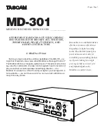
MD-301
Brand: Tascam Pages: 6

iXm
Brand: Yellowtec Pages: 52

ICD-P620
Brand: Sony Pages: 2

ICD-P330F - Ic Recorder
Brand: Sony Pages: 2

ICD-P320 Digital Voice Editor 2
Brand: Sony Pages: 2

ICD-P28 Digital Voice Editor 2
Brand: Sony Pages: 2

ICD-P320 Digital Voice Editor 2
Brand: Sony Pages: 2

ICD-P210 Digital Voice Editor 2
Brand: Sony Pages: 2

ICD-P210
Brand: Sony Pages: 2

ICD-P17 - Ic Recorder
Brand: Sony Pages: 2

ICD-P110VTP
Brand: Sony Pages: 2

ICD-P17 - Ic Recorder
Brand: Sony Pages: 2

ICD-MS515VTP Dragon Naturally Speaking 6
Brand: Sony Pages: 2

ICD-BX800
Brand: Sony Pages: 2


