background image

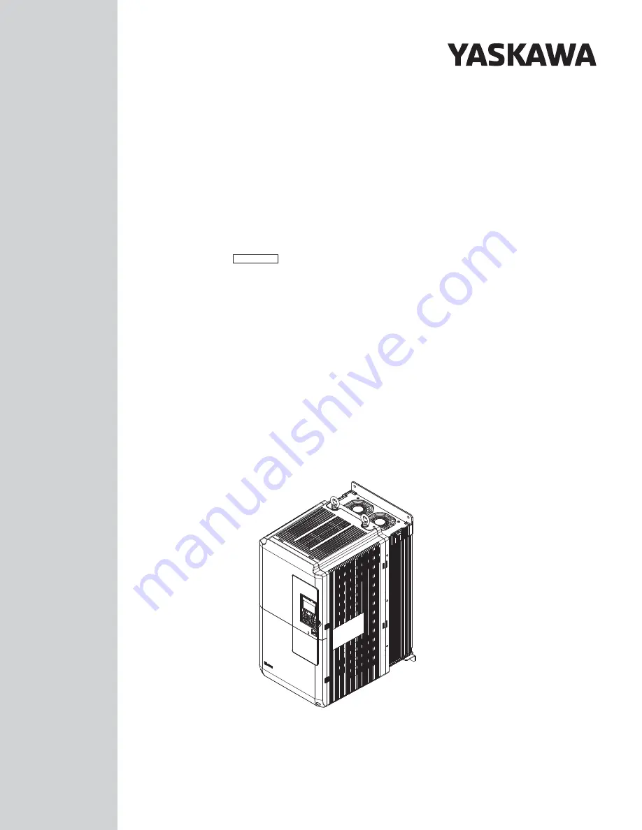
Z1000U HVAC MATRIX Drive

Low Harmonic Drive for HVAC Applications

Quick Start Guide

MANUAL NO.   TOEP C710636 11

E

Models: 200 V Class: 7.5 to 75 kW (10 to 100 HP ND)

400 V Class: 5.5 to 260 kW (7.5 to 350 HP ND)

To properly use the product, read this manual thoroughly and retain 
for easy reference, inspection, and maintenance. Ensure the end user 
receives this manual.

Type: CIMR-ZU

Summary of Contents for Z1000U Series

Page 1: ...MANUAL NO TOEP C710636 11E Models 200 V Class 7 5 to 75 kW 10 to 100 HP ND 400 V Class 5 5 to 260 kW 7 5 to 350 HP ND To properly use the product read this manual thoroughly and retain for easy refere...

Page 2: ...ise without the prior written permission of Yaskawa No patent liability is assumed with respect to the use of the information contained herein Moreover because Yaskawa is constantly striving to improv...

Page 3: ...NICAL INSTALLATION 15 i 4 ELECTRICAL INSTALLATION 19 i 5 START UP PROGRAMMING AND OPERATION 45 i 6 TROUBLESHOOTING 63 i 7 DRIVE SPECIFICATIONS 70 i 8 PARAMETER TABLE 72 i 9 STANDARDS COMPLIANCE 80 i Y...

Page 4: ...1000U HVAC MATRIX Drive User Manual TOEPC71063610 This manual contains detailed information on fault diagnostics parameter settings and BACnet specifications The most recent version of this manual is...

Page 5: ...trol circuit DC voltage is below 50 Vdc To prevent electric shock wait for at least the time specified on the warning label once all indicators are OFF measure for unsafe voltages to confirm the drive...

Page 6: ...ltage of the drive matches the voltage of the incoming power supply before applying power Do not use improper combustible materials Failure to comply could result in death or serious injury by fire At...

Page 7: ...d Output Current Make sure that the motor rated current is less than the rated output current for the drive When 2 Seconds is Required for Momentary Power Loss Ride Thru Time Use the units listed belo...

Page 8: ...e than when running from line power To achieve a higher starting torque use a larger drive or a drive and motor with larger capacity Emergency Stop During a drive fault condition the output shuts off...

Page 9: ...e after shutting off the power Wait for at least the amount of time specified on the drive before touching any components after shutting off the power Failure to comply may cause injury to personnel f...

Page 10: ...oop Vector control can help reduce motor oscillation Take particular caution when adding a variable speed drive to an application running a motor from line power at a constant speed If resonance occur...

Page 11: ...ption card Geared Motor Make sure that the gear and the lubricant are rated for the desired speed range to avoid gear damage when operating at low speeds or very high speeds Consult with the manufactu...

Page 12: ...from power supply please wait 5 minutes before inspecting performing maintenance or wiring the converter Risk of electric shock Hot Surfaces Wait 5 minutes or longer until the unit has cooled To confo...

Page 13: ...1 Kurosaki shiroishi Yahatanishi Ku Kitakyushu 806 0004 Japan MADE IN JAPAN AC3PH 380 500V 50 60Hz 10A AC3PH 0 475V 0 400Hz 11A 20 kg 6W3050 2 100 J0065F575310100 E131457 PASS MODEL C C CIMR ZU4U0011...

Page 14: ...ase 200 V Class Table i 1 Model Number and Specifications 200 V Class Drive Model Reference Motor Capacity kW HP Rated Output Current A 2o0028 7 5 10 28 2o0042 11 15 42 2o0054 15 20 54 2o0068 18 5 25...

Page 15: ...h derating Vibration 10 to 20 Hz 9 8 m s2 2o0028 to 2o0248 4o0011 to 4o0414 20 to 55 Hz 5 9 m s2 2o0028 to 2o0081 4o0011 to 4o0077 20 to 55 Hz 2 0 m s2 2o0104 to 2o0248 4o0096 to 4o0414 Orientation In...

Page 16: ...talling the drive WARNING Crush Hazard Observe the following instructions and precautions Failure to comply could result in serious injury or death from falling equipment Only use vertical suspension...

Page 17: ...8 to 2o0130 and 4o0011 to 4o0124 WARNING Crush Hazard Use an adequate length of wire to ensure a 50 or wider suspension angle as illustrated in Figure i 9 The maximum allowable load of the eye bolts c...

Page 18: ...F Figure i 10 Location of Hanging Brackets Drive Models 2o0154 to 2o0248 and 4o0156 to 4o0414 2 Pass wire through the holes of all four hanging brackets Suspending angle 50 or greater Figure i 11 Driv...

Page 19: ...ure to comply will prevent the automatic fault restart function from working properly NOTICE Inadequate wiring could result in damage to the drive Install adequate branch circuit short circuit protect...

Page 20: ...ne main circuit terminal control circuit terminal M3 M4 Multi function relay output Through Mode H2 02 250 Vac maximum 1 A 30 Vdc maximum 1 A minimum 5 Vdc 10 mA SP SN 6 FM AM 8 9 MFAO 2 Output curren...

Page 21: ...A Never short terminals V or AC as it can cause erroneous operation or damage the drive 5 Set jumper S1 to select between a voltage or current input signal to terminal A2 The default setting is for cu...

Page 22: ...T L3 Main circuit power supply input Connects line power to the drive 20 U T1 V T2 W T3 Drive output Connects to the motor p1 n1 Momentary power loss recovery unit input DC voltage terminals that con...

Page 23: ...rrent ratings using 75 C 167 F 600 Vac vinyl sheathed wire assuming ambient temperature within 40 C 104 F and wiring distance less than 100 m Consider the amount of voltage drop when selecting wire ga...

Page 24: ...6 to 3 16 5 10 to 25 8 to 3 M6 16 6 10 to 25 8 to 3 10 8 10 to 25 8 to 3 M8 8 8 to 10 8 78 1 to 95 5 p1 n1 2 5 14 2 5 to 4 14 to 12 2 5 14 2 5 to 4 14 to 12 M4 1 to 1 4 8 9 to 12 4 2o0068 R L1 S L2 T...

Page 25: ...1 2 to 2 0 10 4 to 17 4 2o0248 R L1 S L2 T L3 70 2 2 0 2P 35 to 95 2 1 to 4 0 2P 50 2P 1 0 2P 35 to 95 2P 1 to 4 0 2P M10 15 to 20 130 to 173 U T1 V T2 W T3 70 2 2 0 2P 35 to 95 2 1 to 4 0 2P 50 2P 1...

Page 26: ...12 4 4o0040 R L1 S L2 T L3 10 8 10 to 25 8 to 3 10 8 6 to 25 10 to 3 M6 4 to 6 35 4 to 53 1 U T1 V T2 W T3 10 8 10 to 25 8 to 3 10 8 6 to 25 10 to 3 M6 10 8 10 to 25 10 to 3 10 8 6 to 25 10 to 3 M8 8...

Page 27: ...o 95 2P 3 to 4 0 2P M10 15 to 20 130 to 173 U T1 V T2 W T3 35 2 2 2P 25 to 95 2 3 to 4 0 2P 25 2P 3 2P 25 to 95 2P 3 to 4 0 2P M10 25 3 25 to 70 4 to 2 0 25 3 25 to 70 3 to 2 0 M10 17 7 to 22 6 156 to...

Page 28: ...should match Failure to comply with proper wiring practices may cause the motor to run in reverse if the phase order is backward NOTICE Do not connect phase advancing capacitors or LC RC noise filters...

Page 29: ...6 Multi function input 6 Multi step speed reference 2 S7 Multi function input 7 Jog reference S8 Multi function input 8 Baseblock command N O SC Multi function input common Multi function input common...

Page 30: ...al relay outputs that involve frequent switching as doing so may shorten relay performance life Switching life is estimated at 200 000 times assumes 1 A resistive load n Serial Communication Terminals...

Page 31: ...al Block Terminal Scre w Size Tightening Torque N m lb in Bare Wire Terminal Ferrule Type Terminal Wire Type Recomm wire size mm2 AWG Applicable wire size mm2 AWG Recomm wire size mm2 AWG Applicable w...

Page 32: ...prevent contact with other signal lines and equipment Improper wiring practices could result in drive or equipment malfunction due to short circuit NOTICE Connect the shield of shielded cable to the...

Page 33: ...e the wire jumper between terminals SC and SP or SC and SN to select between Sink mode Source mode or external power supply for the digital inputs S1 to S8 as shown in Table i 12 Default Sink mode int...

Page 34: ...mA 0 to 3 0 H3 05 Terminal A3 signal level selection Selects the signal level for terminal A3 0 0 to 10 Vdc 1 0 to 10 Vdc Bipolar 2 4 to 20 mA 3 0 to 20 mA 0 to 3 0 H3 09 Terminal A2 signal level sele...

Page 35: ...he specified torque Completely removing the screws or tightening the screws to an incorrect torque may cause drive failure NOTICE Prevent Drive Damage Install the two EMC filter screws in the same pos...

Page 36: ...er Drives ship from the factory with EMC filter screws installed in the OFF position L1 L2 L3 Figure i 23 Symmetrical Grounded Network n EMC Filter Switch Location ON OFF SW A B E G IG R R S S S1 S2 S...

Page 37: ...ch Location Drive Models 2E0042 2W0042 2E0054 2W0054 4E0040 to 4E0077 and 4W0040 to 4W0077 ON OFF SW A B A SW ON B Screw OFF Figure i 26 EMC Filter Switch Location Drive Models 2E0104 2W0104 2E0130 2W...

Page 38: ...0154 2E0192 2W0192 4E0156 4W0156 4E0180 and 4W0180 B A B A A SW ON B Screw OFF Figure i 28 EMC Filter Switch Location Drive Models 2E0248 2W0248 4EU0216 4W0216 4E0240 and 4W0240 i 4 Electrical Install...

Page 39: ...does not provide power to the main circuit of the drive It is possible to read fault and parameter data in the drive via the operator or network communications when the drive switches to the 24 V Con...

Page 40: ...i 32 24 V Control Power Supply Unit Location Models 2P0104 2W0104 2P0130 2W0130 4P0096 4W0096 4P0124 and 4W0124 A A Power Supply Terminal Block TB1 Figure i 33 24 V Control Power Supply Unit Location...

Page 41: ...the 24 0 and FE terminals as shown in Figure i 36 then tighten the terminal screws to hold wiring in place Refer to Table i 20 to confirm that the proper tightening torque is applied to each terminal...

Page 42: ...Applicable Gauges mm2 AWG Recomm Gauge mm2 AWG Applicable Gauges mm2 AWG 24 0 FE M2 0 22 to 0 25 1 95 to 2 21 0 75 18 AWG Stranded wire 0 25 to 1 0 24 to 17 AWG Solid wire 0 25 to 1 5 24 to 16 AWG 0 5...

Page 43: ...range of the drive 6 The voltage rating for the motor should match the drive output specifications 13 7 Verify that the drive is properly sized to run the motor Main Circuit Wiring 8 Confirm proper br...

Page 44: ...For 3 Wire sequence set parameters for multi function contact input terminals S1 to S8 and wire control circuits 21 Properly wire the option card 32 22 Check for any other wiring mistakes Only use a...

Page 45: ...O mode Run command input source depends on b1 02 Frequency reference input source depends on b1 01 5 Up Arrow Key Scrolls up to display the next item selects parameter numbers and increments setting v...

Page 46: ...when the frequency reference is assigned to the MEMOBUS Modbus Communication Inputs of the drive OP Displayed when the frequency reference is assigned to an option card connected to the drive 6 LO RE...

Page 47: ...when in Frequency Reference Mode and Monitor Mode u AUTO LED and HAND LED Indications Table i 25 AUTO LED and HAND LED Indications AUTO LED HAND LED State AUTO Off HAND Off OFF mode AUTO Off HAND On s...

Page 48: ...d X Parameters LSEQ LREF LSEQ LREF LSEQ LREF LSEQ LREF LSEQ LREF LSEQ LREF YASKAWA Z1000U XXXV XXXHP XXXA XXXXXXXXX CIMR ZXXXXXXXXX Initial Display 5 6 Programming Mode 2 Drive Mode 1 FWD FWD FWD FWD...

Page 49: ...ve is ready to run the application E1 01 for input voltage setting Figure i 42 Basic Start Up n Powering Up the Drive Review the following checklist before turning the power on Item to Check Descripti...

Page 50: ...ed by the user as User Settings User Settings are stored when parameter o2 03 is set to 1 Set defaults Note User Initialization resets all parameters to a user defined set of default values previously...

Page 51: ...FF indicator will flash No Parameter Name Setting Range Default b1 01 Frequency Reference Selection for AUTO Mode 0 to 3 1 Setting 0 HOA Keypad Using this setting the frequency reference can be input...

Page 52: ...I A1 A2 A3 Figure i 44 Setting the Frequency Reference as a Current Signal to Terminal A2 Switching between Main Auxiliary Frequency References The frequency reference input can be switched between t...

Page 53: ...instructions on integrating the drive into the communication system Note If b1 02 is set to 3 but an option card is not installed in CN5 an oPE05 operation error will be displayed on the HOA keypad an...

Page 54: ...ed It can be calculated by DC Injection brake time b2 04 x 10 x Output frequency Maximum output frequency E1 04 Output frequency when Stop command was entered 100 Maximum output frequency 10 DC Inject...

Page 55: ...erate from 0 Hz to the maximum output frequency E1 04 Deceleration time parameters always set the time to decelerate from maximum output frequency to 0 Hz C1 01 and C1 02 are the default active accel...

Page 56: ...ng between each frequency reference The Jog frequency overrides all other frequency references and must be selected by a separate digital input The multi speed references 1 and 2 can be provided by an...

Page 57: ...frequency references Even if the frequency reference is set to a higher value the drive internal frequency reference will not exceed this value No Parameter Name Setting Range Default d2 01 Frequency...

Page 58: ...ock Command 1 Number appearing in parenthesis is the default value after performing a 3 Wire initialization A1 03 3330 n H2 01 to H2 03 Terminal M1 M2 M3 M4 and MD ME MF Function Selection No Paramete...

Page 59: ...er a motor overload fault oL1 A fault is output and the motor will coast to stop Setting 4 PM Derated Torque Motor Use this setting when operating a PM motor PM motors for derated torque have a self c...

Page 60: ...The motor overheat alarm level triggers an oH3 alarm and the drive continues the operation selected in L1 03 The overheat fault level triggers an oH4 fault outputs a fault signal and the drive stops...

Page 61: ...drive is used in V f Control and other Auto Tuning selections are not possible Drive and motor capacities differ Tunes the drive after the cable between the drive and motor has been replaced with a ca...

Page 62: ...cillation or vibration Correct any problems that occur with hunting oscillation and other control related issues Refer to the User Manual for details u Test Run Checklist Review the checklist before p...

Page 63: ...proximately 150 Vrms 400 V Class Approximately 300 Vrms bAT HOA Keypad Battery Low bUS Option Communication Error The connection was lost after establishing initial communication Only detected when th...

Page 64: ...tion GF Ground Fault A current short to ground exceeded 50 of rated current on the output side of the drive Setting L8 09 to 1 enables ground fault detection LF Output Phase Loss Phase loss on the out...

Page 65: ...load protection tripped oL2 Overload The thermal sensor of the drive triggered overload protection oL3 Overtorque Detection 1 The current has exceeded the value set for Torque Detection Level 1 L6 02...

Page 66: ...u Alarm Detection n Alarm Codes An alarm is indicated by a code on the data display and the flashing ALM LED The drive output is not necessarily switched off To remove an alarm trace and remove the c...

Page 67: ...back level is below the detection level set to b5 13 for longer than the time set to b5 14 Fdv Power Supply Frequency Fault The input power supply frequency exceeded the allowable frequency fluctuatio...

Page 68: ...set to an inappropriate value The drive will not operate until the parameter or parameters causing the problem are set correctly An oPE however does not trigger an alarm or fault output When an oPE a...

Page 69: ...larm Er 01 Motor Data Error Er 02 Minor Fault Er 03 STOP Button Input Er 04 Line to Line Resistance Error Er 05 No Load Current Error Er 08 Rated Slip Error Er 09 Acceleration Error Er 12 Current Dete...

Page 70: ...cel decel 3 Wire Sequence Auto Tuning Stationary for Line to Line Resistance Rotational for V f Control Cooling Fan on off Switch Slip Compensation Torque Compensation Frequency Jump Upper lower Limit...

Page 71: ...tings Specifications may vary with different motors and with changing motor temperature Contact Yaskawa for consultation 3 Overload protection may be triggered when operating with 150 of the rated out...

Page 72: ...b1 17 Run Command at Power Up 0 Disregarded A new Run command must be issued after power up 1 Allowed Motor will start immediately after power up if a Run command is already enabled b2 01 DC Injection...

Page 73: ...nooze function b5 16 PID Sleep Delay Time Sets a delay time before the sleep snooze function is triggered No Name Description b5 17 PID Accel Decel Time Sets the acceleration and deceleration time to...

Page 74: ...teristic at Accel Start S curve at acceleration start C2 02 S Curve Characteristic at Accel End S curve at acceleration end No Name Description C6 02 Carrier Frequency Selection 1 4 0 kHz 2 6 0 kHz 3...

Page 75: ...1 Bit Select Sets the bits for the MEMOBUS Modbus registers from which data will be sent to contact outputs 62 and 162 H2 09 MEMOBUS Register 2 Address Select Sets the addresses of the MEMOBUS Modbus...

Page 76: ...changes to parameter settings 1 Parameter changes are activated immediately without the Enter command H5 12 Run Command Method Selection 0 FWD Stop REV Stop 1 Run Stop FWD REV L1 01 Motor Overload Pro...

Page 77: ...Disabled 1 Enabled No Name Description L8 06 Input Phase Detection Level When ripple is observed in the DC bus expansion of the input bias is calculated This value becomes the input phase if the diffe...

Page 78: ...he user to set values that can be used as reference information o1 19 User Defined Parameter Lower Allows the user to set values that can be used as reference information o2 02 OFF Key Function Select...

Page 79: ...l Status Displays the input terminal status U1 10 00000000 Digital input 1 terminal S1 enabled Digital input 2 terminal S2 enabled Digital input 3 terminal S3 enabled Digital input 4 terminal S4 enabl...

Page 80: ...ory 3 in accordance with IEC EN 60664 n Grounding The drive is designed to be used in T N grounded neutral point networks If installing the drive in other types of grounded systems contact your Yaskaw...

Page 81: ...standards and local safety regulations WARNING Electrical Shock Hazard Because the leakage current exceeds 3 5 mA in models 4o0302 and larger IEC EN 61800 5 1 2007 states that either the power supply...

Page 82: ...dicates that UL has performed product testing and evaluation and determined that their stringent standards for product safety have been met For a product to receive UL certification all components ins...

Page 83: ...ST and Tokyo DIP or equivalent for the insulation cap Table i 33 matches the wire gauges and terminal screw sizes with Yaskawa recommended crimp terminals tools and insulation caps Use the appropriate...

Page 84: ...267 4 0 R100 10 YF 1 TD 324 TP 100 100 051 269 2o0192 3 M10 R22 10 YA 5 AD 953 TP 022 100 061 113 2 R38 10 AD 954 TP 038 100 061 114 1 2 1 0 R60 10 AD 955 TP 060 100 051 266 2 0 70 10 YF 1 YET 300 1...

Page 85: ...YA 5 AD 952 TP 014 100 051 261 4 2 R22 6 AD 953 TP 022 100 051 262 3 4o0077 4 M6 R22 6 YA 5 AD 953 TP 022 100 051 262 3 2 4o0096 8 M8 R8 8 YA 4 AD 901 TP 008 100 601 111 6 R14 8 AD 902 TP 014 100 054...

Page 86: ...10 TD 322 TD 311 TP 080 100 064 251 3 0 2 80 10 TD 323 TD 312 100 051 267 4 0 R100 10 TD 324 TD 312 TP 100 100 051 269 4o0361 3 0 M10 80 10 YF 1 YET 300 1 TD 323 TD 312 TP 080 100 051 267 4 0 2 R100...

Page 87: ...rated current to parameter E2 01 n L1 01 Motor Overload Protection Selection The drive has an electronic overload protection function oL1 based on time output current and output frequency that protect...

Page 88: ...200 Figure i 62 Motor Overload Protection Time n L1 03 Motor Overheat Alarm Operation Selection PTC input Sets the drive operation when the PTC input signal reaches the motor overheat alarm level oH3...

Page 89: ...ified fuses n Main Circuit Terminal Wiring Yaskawa recommends using closed loop crimp terminals on all drive models To maintain CSA approval CSA Certified closed loop crimp terminals are specifically...

Page 90: ...wed and corrected documentation Standards Compliance Revision CSA Standards Compliance Back Cover Revision Address Format January 2015 2 Front Cover Revision Models Receiving Revision Reference Motor...

Page 91: ...This Page Intentionally Blank YASKAWA ELECTRIC TOEP C710636 11E Z1000U HVAC MATRIX Drive Quick Start Guide 91...

Page 92: ...017 0099 Fax 66 2 017 0799 http www yaskawa co th YASKAWA ELECTRIC CHINA CO LTD 22F One Corporate Avenue No 222 Hubin Road Shanghai 200021 China Phone 86 21 5385 2200 Fax 86 21 5385 3299 http www yas...

Reviews: