YASKAWA SOLECTRIA XGI 1500 Series, Installation And Operation Manual
The YASKAWA SOLECTRIA XGI 1500 Series is a high-quality solar inverter designed for maximum energy production. For detailed instructions on installation and operation, download the free Installation And Operation Manual available at manualshive.com. This comprehensive manual will ensure smooth setup and optimal performance of your solar system.
Share
Download


Reviews:
No comments
Related manuals for SOLECTRIA XGI 1500 Series

blueplanet 3.0 NX1 M2
Brand: Kaco Pages: 33

Powador 1501xi
Brand: Kaco Pages: 15

blueplanet 110 TL3
Brand: Kaco Pages: 119

Z3-HE4K-01
Brand: Z3 Technology Pages: 27

ETH-FE1
Brand: Black Iris For Telecom & Technology Pages: 14

DA1-34072FB-B20C
Brand: Eaton Pages: 16

R6 S2 Series
Brand: SAJ Pages: 32

MONOGIZER 200
Brand: Audioplex Pages: 2

BTNA-70
Brand: BASETech Pages: 8

PS028
Brand: Mayty Pages: 14

Tsunami TSU-AT1000
Brand: SoundTraxx Pages: 6
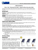
SPEPSN-HRN-PA
Brand: Larson Electronics Pages: 3

ACP-09CH25AEMI/I
Brand: M Design Pages: 89

10059:AEG
Brand: AEG Pages: 150

570-1000 Revision A
Brand: ARTEX Pages: 28

EOP0002C01
Brand: Albalá Ingenieros Pages: 28

C 658
Brand: NAD Pages: 22

LV Series
Brand: MYERS Pages: 19


