background image

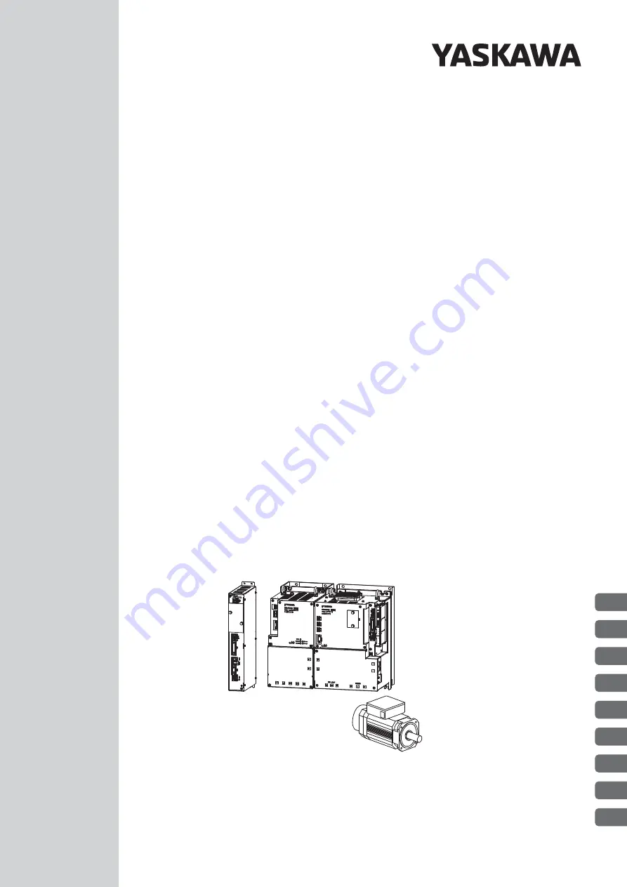
Multi-Winding Drive Unit Model: JUSP-MD

D



A

SERVOPACK Model: SGDV-



J

Converter Model: SGDV-COA
Servomotor Model: SGMVV

Multi-Winding Drive Unit

Rotational Motor
MECHATROLINK-

II

 Communications References

-

V

 Series

AC Servo Drives

USER’S MANUAL

For Use with Large-Capacity Models

Design and Maintenance

MANUAL NO.   SIEP S800001 69D

1

2

3

4

5

6

7

8

9

Outline

Panel Operator

Wiring and Connection

Operation

Adjustments

Utility Functions (Fn



)

Monitor Displays (Un



)

Troubleshooting

Appendix

Summary of Contents for Sigma-V JUSP-MD D A Series

Page 1: ...nit Rotational Motor MECHATROLINK II Communications References V Series AC Servo Drives USER S MANUAL For Use with Large Capacity Models Design and Maintenance MANUAL NO SIEP S800001 69D 1 2 3 4 5 6 7 8 9 Outline Panel Operator Wiring and Connection Operation Adjustments Utility Functions Fn Monitor Displays Un Troubleshooting Appendix ...

Page 2: ... liability is assumed with respect to the use of the information contained herein Moreover because Yaskawa is con stantly striving to improve its high quality products the information contained in this manual is subject to change without notice Every precaution has been taken in the preparation of this manual Nevertheless Yaskawa assumes no responsibility for errors or omissions Neither is any lia...

Page 3: ...i winding drive unit SERVO PACKs and converters Servo System A servo control system that includes the combination of a servo drive with a host controller and peripheral devices Analog pulse model A multi winding drive unit with an analog voltage or pulse train refer ence interface M II model A multi winding drive unit with a MECHATROLINK II communica tions reference interface Servo ON Power to mot...

Page 4: ... parameter will be effective Indicates the parameter classification Indicates the minimum setting unit for the parameter Torque Position Speed Indicates the setting range for the parameter The notation n indicates a parameter for selecting functions Each corresponds to the setting value of that digit The notation shown here means that the third digit is 1 This section explains the selections for t...

Page 5: ...ls Design and Maintenance Multi Winding Drive System Rotational Motor MECHATROLINK II Communications References this manual Σ V Series DC Power Input Σ V Series Σ V Series for Large Capacity Models User s Manual MECHATROLINK II Commands No SIEP S800000 54 Σ V Series User s Manual Operation of Digital Operator No SIEP S800000 55 AC Servomotor Safety Precautions No TOBP C230200 00 Σ V Series Safety ...

Page 6: ...ssibly result in loss of life or serious injury Indicates precautions that if not heeded could result in relatively serious or minor injury damage to the product or faulty operation In some situations the precautions indicated could have serious consequences if not heeded Indicates prohibited actions that must not be performed For example this symbol would be used to indicate that fire is prohibit...

Page 7: ...e sure to make the system modifications The multi turn limit value need not be changed except for special applications Changing it inappropriately or unintentionally can be dangerous If the Multiturn Limit Disagreement alarm occurs check the setting of parameter Pn205 in the multi winding drive unit to be sure that it is correct If Fn013 is executed when an incorrect value is set in Pn205 an incor...

Page 8: ...etic contactor is turned OFF Installation disassembly or repair must be performed only by authorized personnel Failure to observe this warning may result in electric shock or injury The person who designs a system using the safety function Hard Wire Baseblock function must have full knowledge of the related safety standards and full understanding of the instructions in this manual Failure to obser...

Page 9: ...than fumigation must be used Example Heat treatment where materials are kiln dried to a core temperature of 56 C for 30 minutes or more If the electronic products which include stand alone products and products installed in machines are packed with fumigated wooden materials the electrical components may be greatly damaged by the gases or fumes resulting from the fumigation process In particular d...

Page 10: ...er opening in the main circuit terminals Make sure that no part of the core wire comes into contact with i e short circuits adjacent wires Install a battery at either the host controller or the multi winding drive unit but not both It is dangerous to install batteries at both ends simultaneously because that sets up a loop circuit between the batteries Always use the specified power supply voltage...

Page 11: ...l stop in the zero clamp state when overtravel occurs Failure to observe this caution may cause workpieces to fall due to overtravel Before you start operation always set the moment of inertia ratio Pn103 correctly Setting to an incorrect moment of inertia ratio may cause vibration Do not touch the SERVOPACK or converter heat sink regenerative resistor or motor while power is ON or soon after the ...

Page 12: ... are sometimes shown without covers or protective guards Always replace the cover or protective guard as specified first and then operate the products in accordance with the manual The drawings presented in this manual are typical examples and may not match the product you received If the manual must be ordered due to loss or damage inform your nearest Yaskawa representative or one of the offices ...

Page 13: ...ed product in a manner in which it was not originally intended 5 Causes that were not foreseeable with the scientific and technological understanding at the time of ship ment from Yaskawa 6 Events for which Yaskawa is not responsible such as natural or human made disasters 2 Limitations of Liability 1 Yaskawa shall in no event be responsible for any damage or loss of opportunity to the customer th...

Page 14: ... property Systems that require a high degree of reliability such as systems that supply gas water or electricity or systems that operate continuously 24 hours a day Other systems that require a similar high degree of safety 4 Never use the product for an application involving serious risk to life or property without first ensuring that the system is designed to secure the required level of safety ...

Page 15: ... MD D SERVOPACKs SGDV J converters SGDV COA Machinery Directive 2006 42 EC EN ISO13849 1 2015 EMC Directive 2014 30 EU EN 55011 group 1 class A EN 61000 6 2 EN 61000 6 4 EN 61800 3 Category C2 Second Environment Low Voltage Directive 2014 35 EU EN 50178 EN 61800 5 1 RoHS Directive 2011 65 EU EN 50581 Servomotors SGMVV EMC Directive 2014 30 EU EN 55011 group 1 class A EN 61000 6 2 EN 61000 6 4 EN 6...

Page 16: ...ance Level Safety Integrity Level IEC 61508 SIL2 IEC 62061 SILCL2 Probability of Dangerous Failure per Hour IEC 61508 IEC 62061 PFH 1 7 10 9 1 h 0 17 of SIL2 Performance Level EN ISO 13849 1 PL d Category 3 Mean Time to Dangerous Failure of Each Channel EN ISO 13849 1 MTTFd High Average Diagnostic Coverage EN ISO 13849 1 DCavg Low Stop Category IEC 60204 1 Stop category 0 Safety Function IEC 61800...

Page 17: ...Drive Unit Model Designation 1 14 1 6 2 SERVOPACK Model Designation 1 15 1 6 3 Converter Model Designation 1 15 1 7 Combinations for Multi Winding Drive Systems 1 16 1 8 Inspection and Maintenance of a Multi Winding Drive System 1 16 Chapter 2 Panel Operator 2 1 2 1 Overview 2 2 2 1 1 Names and Functions 2 2 2 1 2 Display Selection 2 2 2 1 3 Status Display 2 3 2 2 Utility Functions Fn 2 4 2 3 Para...

Page 18: ... Brake Unit 3 35 3 10 4 Setting the Dynamic Brake Answer Function 3 36 3 10 5 Installation Standards 3 37 3 10 6 Connections 3 37 3 11 Noise Control and Measures for Harmonic Suppression 3 41 3 11 1 Wiring for Noise Control 3 41 3 11 2 Precautions on Connecting Noise Filter 3 43 3 11 3 Connecting a Reactor for Harmonic Suppression 3 45 Chapter 4 Operation 4 1 4 1 MECHATROLINK II Communications Set...

Page 19: ... 1 Adjustments 5 2 5 1 2 Basic Adjustment Procedure 5 3 5 1 3 Monitoring Operation during Adjustment 5 4 5 1 4 Safety Precautions on Adjustment of Servo Gains 5 7 5 2 Advanced Autotuning Fn201 5 10 5 2 1 Calculating the Moment of Inertia 5 10 5 2 2 Procedure for Calculating the Moment of Inertia 5 11 5 3 One parameter Tuning Fn203 5 14 5 3 1 One parameter Tuning 5 14 5 3 2 One parameter Tuning Pro...

Page 20: ...lays 7 2 7 2 Viewing Monitor Displays 7 3 7 3 Monitoring Input Signals 7 4 7 3 1 Interpreting Input Signal Display Status 7 4 7 3 2 Input Signal Display Example 7 4 7 4 Monitoring Output Signals 7 5 7 4 1 Interpreting Output Signal Display Status 7 5 7 4 2 Output Signal Display Example 7 5 7 5 Monitoring Safety Input Signals 7 6 7 5 1 Interpreting Safety Input Signal Display Status 7 6 7 5 2 Safet...

Page 21: ...xxi Index Index 1 Revision History ...

Page 22: ...1 Ratings 1 8 1 4 2 Basic Specifications 1 9 1 4 3 MECHATROLINK II Function Specifications 1 12 1 5 Internal Block Diagrams 1 13 1 5 1 Internal Block Diagram of the Multi Winding Drive Unit 1 13 1 5 2 Internal Block Diagram for SERVOPACK and Converter 1 13 1 6 Model Designations 1 14 1 6 1 Multi Winding Drive Unit Model Designation 1 14 1 6 2 SERVOPACK Model Designation 1 15 1 6 3 Converter Model ...

Page 23: ...nit is connected to the encoder of a servomotor and it performs position speed or torque control It controls the SERVOPACKs through local communications cables SERVOPACKs and Converters The SERVOPACKs and converters drive the servomotor based on references they receive from the multi winding drive unit The following figure shows a system configuration example Type of References MECHATROLINK II ref...

Page 24: ...ecial personal computer cable to make the connection Digital operator connector CN54 Used to connect to a digital operator or personal computer RS422 Connectors for MECHA TROLINK II communica tions CN9A and CN9B Used to connect devices that support MECHA TROLINK II Connector for I O signals CN1 Used to connect sequence I O signals Encoder connector CN21 Connects to the encoder cable CN22 connector...

Page 25: ...1 1 Setting the MECHATROLINK II Com munications Switches S1001 and S1002 DIP switch S1002 Used to make settings for MECHATROLINK II communications 4 1 1 Setting the MECHATROLINK II Com munications Switches S1001 and S1002 MS1 LED indicator This indicator cannot be used MMA MM2 MM3 and MM4 LED indicators Lights yellow during MECHATROLINK II com munications Panel operator keys Used to set parameters...

Page 26: ...t DC voltage input terminals P and N Connect these terminals to P and N on the con verter Dynamic brake unit connection terminals DU DV and DW Use these terminals to connect the dynamic brake unit Do not connect servomotors to these terminals Ground terminal Be sure to connect to protect against electrical shock 3 1 Main Circuit Wiring Plunger Pull it to open the plastic cover for use of the MECHA...

Page 27: ...CN104 are equivalent outputs It is normally not necessary to connect CN104 SERVOPACK converter I O connector CN901 Connect this connector to CN901 on the SERVO PACK Charge indicator Lights orange when the main circuit power sup ply is ON and stays lit as long as the internal capacitor remains charged Therefore do not touch the converter even after the power supply is turned OFF if the indicator is...

Page 28: ...minals P and N is abnormal Converter LED indicator FANSTOP Lights red when an error occurs while the con verter fan is running Converter LED indicator MC FAULT Lights red when an error occurs when the inrush current limit relay is used Main circuit DC voltage output terminals P and N Connect these terminals to P and N on the SER VOPACK Regenerative resistor connecting terminals B1 and B2 Connect e...

Page 29: ...SERVOPACKs and converters are as shown below Refer to 3 9 Selecting and Connecting a Regenerative Resistor Unit for details Model JUSP MD D 3D Control Power Supply 24 VDC 15 to 15 0 6 A Overvoltage Category III SERVOPACK Model SGDV 101J Converter Model SGDV COA 5EDA Continuous Output Current Arms 98 Instantaneous Max Output Current Arms 230 Regenerative Resistor Unit External Dynamic Brake Unit Ex...

Page 30: ...on Degree 2 Altitude 1 000 m or less Others Free of static electricity strong electromagnetic fields magnetic fields or exposure to radioactivity Mounting Base mounted Approximate Mass 2 6 kg Connectable SERVOPACKs Two large capacity Σ V SERVOPACKs Connection Method with SERVO PACKs Two serial communications ports Each SERVOPACK is connected 1 1 Perfor mance Speed Control Range 1 5000 The lower li...

Page 31: ...BK Warning WARN Near NEAR Signal allocations can be performed and positive and negative logic can be changed Communi cations Function RS422A Communi cations CN54 Interface Digital operator Model JUSP OP05A E personal computer can be connected with SigmaWin 1 N Communica tions N Up to 15 stations possible at RS422A port Axis Address Setting Set by parameter USB Communi cations CN4 Interface Persona...

Page 32: ... 55 C Storage Temperature 20 C to 85 C Ambient Humidity 90 RH or less With no freezing or condensation Storage Humidity 90 RH or less Vibration Resistance 4 9 m s2 Shock Resistance 19 6 m s2 Protection Class IP10 The environment must satisfy the following conditions Free of corrosive or flammable gases Free of exposure to water oil or chemicals Free of dust salts or iron dust Pollution Degree 2 Al...

Page 33: ...s 30 Selected by combining the rotary switch S1001 and the DIP switch S1002 Transmission Speed 10 Mbps Selected with the DIP switch S1002 Transmission Cycle 250 μs 0 5 ms to 4 0 ms Multiples of 0 5 ms Number of Transmission Bytes 17 bytes per station or 32 bytes per station Selected with the DIP switch S1002 Reference Method Control Method Position speed or torque control with MECHATROLINK II comm...

Page 34: ...2 L2 24 V 0 V 㸩 㸫 U V W 5 V Voltage sensor gate drive 1 Voltage sensor Fan 2 L3 MC drive Voltage sensor 2 CHARGE P24 V Fan 1 SPD 㸩 㸫 15 V 24 V 2 P N 24 V 24C 24 V 24C CN103 CN104 CN901 Fan Temperature sensor P N CHARGE Voltage sensor Current sensor Gate drive Fan 4 Fan 3 55 kW models only Temperature sensor Converter I O SERVOPACK control power supply 㸩 㸫 CN103 CN104 P24 V 0 V CN901 Control power ...

Page 35: ...1st 2nd digits MD Multi winding drive unit 5th 6th digits Interface Specifications Code Interface 11 MECHATROLINK II communications reference rotational servomotor 1st 2nd digits 5th 6th digits 7th digit 7th digit Design Revision Order 000 8th 9th 10th digits 00 11th 12th digits 11th 12th digits Software Specification Code Specification 00 Standard 0 13th digit 13th digit Parameter Specification C...

Page 36: ...fication 00 Standard 7th digit Design Revision Order 1st 2nd 3rd digits 4th digit 5th 6th digits 7th digit 101 J F1 A 8th 9th 10th digits 000 8th 9th 10th digits Hardware Specifications Code Specifications 000 Base mounted standard 001 Duct ventilated 002 Varnished 003 Duct ventilated and Varnished 11th 12th digits 00 13th digit 0 13th digit Parameter Specification Code Specification 0 Standard Ro...

Page 37: ...PACKs and Converters Note The standard replacement period is given for usage under the following operating conditions Surrounding air temperature Annual average of 30 C Load factor 80 max Operation rate 20 hours day max Main Circuit Power Supply Voltage Servomotor SERVOPACKs Converters Multi Winding Drive Unit Motor Speed Model SGMVV Capacity Model SGDV Model SGDV COA Model JUSP Three phase 400 VA...

Page 38: ... 1 1 Names and Functions 2 2 2 1 2 Display Selection 2 2 2 1 3 Status Display 2 3 2 2 Utility Functions Fn 2 4 2 3 Parameters Pn 2 5 2 3 1 Parameter Classification 2 5 2 3 2 Notation for Parameters 2 5 2 3 3 Setting Parameters 2 6 2 4 Monitor Displays Un 2 9 ...

Page 39: ...e UP Key and the DOWN Key simultaneously Be sure to remove the cause and then reset the alarm Key No Key Name Function MODE SET Key To select a display To set the set value UP Key To increase the set value DOWN Key To decrease the set value DATA SHIFT Key To display the set value by pressing this key for one second To move to the next digit on the left when flashing Status Display Refer to 2 3 Fn ...

Page 40: ...ting 10 min 1 Always lights in torque control Note If there is noise in the reference voltage during speed control the horizontal line at the far left edge of the panel operator display may flash Refer to 3 11 1 Wiring for Noise Control and take a preventive measures In position control Positioning Completion COIN Lights if error between position reference and actual motor position is less than th...

Page 41: ...play shown on the left appears 5 Pressing the UP Key will rotate the servomotor in the for ward direction Pressing the DOWN Key will rotate the servomotor in the reverse direction The rotation direction of the servomotor changes according to the setting of Pn000 0 as shown in the following table Note Direction when viewed from the load of the servo motor 6 Display flashes When the servomotor origi...

Page 42: ...rameters Parameters for tuning con trol gain and other parame ters Set Pn00B 0 to 1 There is no need to set each parameter individually Pn311 Vibration Detection Sensitivity Setting Range 50 to 500 1 100 Immediately Setting Unit Factory Setting When Enabled Classification Tuning Parameter number Position Torque The control methods for which the parameters applies Speed Speed control Position contr...

Page 43: ...lue for the 1st digit of parameter Pn002 is x Indicates that the value for the 2nd digit of parameter Pn002 is x Pn002 2 x or n x Pn002 3 x or n x Indicates that the value for the 3rd digit of parameter Pn002 is x Indicates that the value for the 4th digit of parameter Pn002 is x Notation Analog Step Display after Operation Keys Operation 1 Press the MODE SET Key to select the parameter setting If...

Page 44: ... Key In this case 6789 is set 3 Press the DATA SHIFT Key The middle four digits will be displayed In this case 0000 is displayed Press the DATA SHIFT Key to move to other digits and change the value by pressing the UP DOWN Key In this case 2345 is set 4 Press the DATA SHIFT Key The top two digits will be displayed In this case 00 is displayed Press the DATA SHIFT Key to move to other digit and cha...

Page 45: ... winding drive unit After the saving is completed press the DATA SHIFT Key for approximately one second Pn522 is displayed again cont d Step Display after Operation Keys Operation MODE SET DATA Step Display after Operation Keys Operation 1 Press the MODE SET Key to select the parameter setting If Pn000 is not displayed press the UP or the DOWN Key to select Pn000 2 Press the DATA SHIFT Key for app...

Page 46: ...le for Motor Rotating Speed The following table outlines the procedures necessary to view the motor rotating speed Un000 Step Display after Operation Keys Operation 1 Press the MODE SET Key to select the monitor display 2 If Un000 is not displayed press the UP or the DOWN Key to select Un000 3 Press the DATA SHIFT Key for approximately one second to display the data of Un000 4 Press the DATA SHIFT...

Page 47: ...put Signal Allocations 3 20 3 4 2 Output Signal Allocations 3 22 3 5 Examples of Connection to Host Controller 3 23 3 5 1 Sequence Input Circuit 3 23 3 5 2 Sequence Output Circuit 3 25 3 6 Wiring MECHATROLINK II Communications 3 27 3 7 Local Communications Cable Connections 3 28 3 8 Encoder Connection 3 29 3 8 1 Encoder Signal CN21 Names and Functions 3 29 3 8 2 Encoder Connection Examples 3 29 3 ...

Page 48: ...n Standards 3 37 3 10 6 Connections 3 37 3 11 Noise Control and Measures for Harmonic Suppression 3 41 3 11 1 Wiring for Noise Control 3 41 3 11 2 Precautions on Connecting Noise Filter 3 43 3 11 3 Connecting a Reactor for Harmonic Suppression 3 45 ...

Page 49: ...the front cover attached when using the SERVOPACK 1 Multi Winding Drive Unit The pin arrangements of the control power supply connectors CN7A CN7B are given below CN7A B Connectors Terminal Name Specifications CN7A B Control power supply input connector CN7A is the 24 VDC 15 to 15 input connector CN7B takes the same input but it is normally not necessary to connect it Ground terminal Connect this ...

Page 50: ...motor terminals CN103 CN104 Control power input connectors CN103 is the 24 VDC 15 input CN104 takes the same input but it is normally not necessary to connect it DU DV DW Dynamic brake unit terminals Connect these terminals to the dynamic brake unit CN115 Dynamic brake unit connector Connect this connector to the DBON and DB24 terminals on the dynamic brake unit NC Do not connect these terminals G...

Page 51: ...utput ter minals Connect these terminals to the P and N terminals on the SERVO PACK Ground terminal Connect this terminal to the power supply ground terminal and then ground it B1 B2 Regenerative resistor connection terminals Connect these terminals to the regenerative resistor unit 1 2 DC reactor connection terminals Remove the short bar before you connect a DC reactor CN103 CN104 Control power o...

Page 52: ...l ducts take into account the reduction of the allowable current Use a heat resistant wire under high surrounding air or panel temperatures where polyvinyl chloride insulated wires will rapidly deteriorate Cable Type Allowable Conductor Temperature C Symbol Name IV 600 V polyvinyl chloride insulated wire 60 HIV 600 V grade heat resistant polyvinyl chloride insulated wire 75 Nominal Cross SectionDi...

Page 53: ... Size in mm2 AWG Connector Model Made by Tyco Electronics Japan G K Connector Model Made by Tyco Electronics Japan G K Connector Model Made by Tyco Electronics Japan G K Control power supply connector CN7A B 1 25 16 175362 1 2P 353717 2 loose contacts 91561 1 Combination of SERVOPACK and Converter 1 Terminal Connector Symbols Screw Size for Terminals Tightening Torque N m HIV Wire Size in mm2 AWG ...

Page 54: ...n of SERVOPACK and Converter Terminal Symbols Screw Size for Terminals Tightening Torque N m Wire Size AWG SGDV 101J SGDV COA5EDA SERVOPACK P N M8 15 0 Bus bar attached to the converter U V W M8 3 0 1 DU DV DW M6 3 0 10 M8 9 0 to 11 0 1 Converter P N M10 12 to 20 Bus bar attached to the converter L1 L2 L3 M10 12 to 20 2 1 2 M10 12 to 20 2 CN101 24 V 0 V Connector 14 B1 B2 M10 12 to 20 8 M8 9 0 to ...

Page 55: ...Crimp Terminal Tools for SERVOPACKs and Converters Model Tools by J S T Mfg Co Ltd Body Head Dies R5 5 6 YHT 2210 R22 10 Body only YPT 150 1 or Body YF 1 Head YET 150 1 TD 223 TD 212 R38 8 R38 10 TD 224 TD 212 R60 8 TD 225 TD 213 70 8 70 10 TD 226 TD 213 ...

Page 56: ...cuit power supply after the control power supply When you turn OFF the power first turn OFF the power for the main circuit and then turn OFF the control power Configure the system so that the control power supply to the multi winding drive unit SERVOPACKs and converters turns ON and OFF at the same time If the control power supply is not turned ON at the same time the following alarms will occur I...

Page 57: ...1A B CN9A B CN54 CN4 CN21 Host controller SERVOPACK 1 CN6 SERVOPACK 2 CN6 CN1 32 31 24 V 1Ry 1D ALM ALM 0 V Power supply Single phase 100 200 VAC 3QF 3FLT 4SA 1KM 2KM 1FLT 2FLT R S T Power supply Three phase 400 VAC 1QF 1SA 1Ry Power supply OFF Power supply ON 3KM 3KM 2Ry 3Ry 1Ry 2Ry 3Ry a b 3KM 5SA 1KM 2SA 2KM 3SA 1PL Thermostat a b 1 1b C B A Molded case circuit breaker Molded case circuit break...

Page 58: ...s insulated from the machine The signal cable conductors are as thin as 0 2 mm2 or 0 3 mm2 Do not impose excessive bending force or tension Use a molded case circuit breaker 1QF or fuse to protect the main circuit The SERVOPACKs and converters connect directly to a commercial power supply They are not isolated through a transformer or other device Always use a molded case circuit breaker 1QF or fu...

Page 59: ...that are compliant with UL standards The table above also provides the nominal values of current capacity and inrush current Select a fuse and a molded case circuit breaker which meet the cutoff characteristics shown below Main circuit control circuit No breaking at three times the current values of the table for 5 s Inrush current No breaking at the same current values of the table for 20 ms Cont...

Page 60: ...t Voltage Combinations Discharging Time min SERVOPACK Model SGDV Converter Model SGDV COA Three phase 400 VAC 101J 5EDA 10 WARNING High voltage may still remain in the SERVOPACKs and converters even after you turn OFF the main circuit power supplies To prevent electric shock do not touch the power supply terminals When the volt age is discharged the charge indicator will turn OFF Make sure the cha...

Page 61: ...RVO PACK and the converter The bus bars can be connected in any direction CN901 I O signal connector between the SERVOPACK and converter CN103 Control power supply input connector I O signal connection cable 24 VDC control power supply cable SERVOPACK Converter M II Cable Name Cable Model Cable Length Description IO signal connection cable JZSP CVI02 A4 E 0 4 m This cable connects the CN901 connec...

Page 62: ...n prohibited Reverse run prohibited With overtravel prevention Stops servomotor when movable part travels beyond the allowable range of motion 4 3 1 DEC SI1 41 Homing deceleration switch signal Connects the deceleration limit switch for homing EXT1 EXT1 7 8 External latch signal 1 Connects the external signals that latch the current feedback pulse counter EXT2 EXT2 11 12 External latch signal 2 EX...

Page 63: ...o ready Torque limit Speed limit detection Warning Near The allocation of an output signal to a pin can be changed in accordance with the function required PAO PAO 33 34 Phase A signal Encoder output pulse signals for two phase pulse train with 90 phase differential 4 4 4 4 6 5 PBO PBO 35 36 Phase B signal PCO PCO 19 20 Phase C signal Origin pulse output signal PL1 PL2 PL3 3 13 18 External latch p...

Page 64: ...safety function signals can be connected only to a SERVOPACK Do not use pins 1 and 2 because they are connected to the internal circuits Signal Name Pin No Function HWBB1 4 Hard wire baseblock input 1 For hard wire baseblock input Baseblock motor current off when OFF HWBB1 3 HWBB2 6 Hard wire baseblock input 2 HWBB2 5 EDM1 8 Monitored circuit status output 1 ON when the HWBB1 and the HWBB2 signals...

Page 65: ...equence signals External latch signal 1 Latched when ON Reverse run prohibited Prohibited when OFF External latch signal 2 Latched when ON External latch signal 3 Latched when ON Backup battery 2 8 to 4 5 V Forward run prohibited Prohibited when OFF Servo alarm output OFF for an alarm Photocoupler output Max operating voltage 30 VDC Max output current 50 mA DC 2 Encoder output pulse phase A Encode...

Page 66: ...ting is absolutely necessary check the operation and confirm that there are no safety problems When two or more signals are allocated to the same input circuit input signal level is valid for all allocated signals resulting in an unexpected machine operation Input Signal Names and Parameters Validity Level Input Signal CN1 Pin Numbers Connection Not Required SERVOPACK judges the connec tion 40 41 ...

Page 67: ...4 5 6 7 8 L P OT 9 A B C D E F Reverse Run Prohibited Pn50B 0 H N OT 0 1 2 3 Factory setting 4 5 6 7 8 L N OT 0 A B C D E F Forward External Torque Limit Pn50B 2 L P CL 0 1 2 3 4 5 6 7 8 Factory setting H P CL 9 A B C D E F Reserve External Torque Limit Pn50B 3 L N CL 0 1 2 3 4 5 6 7 8 Factory setting H N CL 0 A B C D E F Homing Deceleration LS Pn511 0 L DEC 0 1 Factory setting 2 3 4 5 6 7 8 H DEC...

Page 68: ...utput Signal Names and Parameters Output Signal CN1 Pin Numbers Invalid not use 25 26 27 28 29 30 Positioning Completion Pn50E 0 COIN 1 2 3 0 Factory setting Speed Coincidence Detection Pn50E 1 V CMP 1 2 3 0 Factory setting Rotation Detection Pn50E 2 TGON 1 2 3 0 Factory setting Servo Ready Pn50E 3 S RDY 1 2 3 0 Factory setting Torque Limit Detection Pn50F 0 CLT 1 2 3 0 Factory setting Speed Limit...

Page 69: ...0 mA minimum The multi winding drive unit s input circuit uses a bidirectional photocoupler Select either the sink circuit or the source circuit according to the specifications required for each machine Note The connection example in 3 3 3 shows sink circuits The ON OFF polarity differs between when a sink circuit is connected and when a source circuit is connected Relay Circuit Example Open colle...

Page 70: ...ction signals can be connected only to a SERVOPACK Input Signal Connection Example 24 V power supply Fuse Switch 0 V Motor HWBB1 HWBB1 HWBB2 HWBB2 SERVOPACK 1 Converter 1 Control circuit Control circuit Block Block Power supply Power module Power module Run signal Run signal CN8 CN8 4 3 6 5 HWBB1 HWBB1 HWBB2 HWBB2 SERVOPACK 2 Converter 2 Block Block Power supply 4 3 6 5 ...

Page 71: ...phase A signal 35 36 phase B signal and 19 20 phase C signal are explained below These terminals output the following signals via the line driver output circuits Output signals for which encoder serial data is converted as two phases pulses PAO PAO PBO PBO Origin pulse signals PCO PCO Connect the line driver output circuit through a line receiver circuit at the host controller Incorrect wiring or ...

Page 72: ...f EDM1 signal are as follows SERVOPACK 1 CN8 CN8 8 24 V power supply EDM1 7 0 V Host controller EDM1 SERVOPACK 2 8 EDM1 7 EDM1 Type Signal Name Pin No Output Status Meaning Output EDM1 CN8 8 CN8 7 ON Both the HWBB1 and HWBB2 signals are working nor mally OFF The HWBB1 signal the HWBB2 signal or both are not working normally Items Characteristic Remarks Maximum Allowable Voltage 30 VDC Maximum Curr...

Page 73: ...d Note 1 The length of the cable between stations L1 L2 Ln must be 0 5 m or more 2 The total cable length must be L1 L2 Ln 50 3 When multiple multi winding drive units or SERVOPACKs are connected by MECHATROLINK II communica tions cables a terminator must be installed at the final multi winding drive unit or SERVOPACK Terminator Option Option Ln L1 L2 DC24V DC 0V MP2300 YASKAWA TEST ࠉ ࠉ ࠉ RDY ALM ...

Page 74: ...ve unit and SERVOPACK are 1 1 so two communications ports are provided on the multi winding drive unit Note 1 Attach a terminator to the CN6B connector on the SERVOPACK 2 The CN41A CN41B connectors are the same connectors as the CN9A CN9B connectors for MECHATROLINK II communications Make sure you connect them correctly 3 The maximum length of a local communications cable is 3 m Multi winding Driv...

Page 75: ... To prevent the influence of external noise we recommend you connect a ferrite core on the motor end of the encoder cable using two turns 3 represents shielded twisted pair wires Signal Name Pin No Function PG 5 V 1 Encoder power supply 5 V PG 0 V 2 Encoder power supply 0 V BAT 3 Battery BAT 4 Battery PS 5 Serial data PS 6 Serial data Shield Shell 35 0 V SG 1 PAO PAO PBO PBO PCO PCO 1 2 5 6 CN21 3...

Page 76: ...log for details When Installing a Battery on the Host Controller Insert a diode near the battery to prevent reverse current flow PCO 21 22 BAT BAT 33 34 35 36 19 20 CN1 PAO PAO PBO PBO PCO Multi winding drive unit Phase A Phase B Phase C Connector shell CN1 3 4 Host controller Battery Phase A Phase B Phase C R R R R terminating resistance 220 to 470 Ω Applicable line receiver SN75ALS175 or MC3486 ...

Page 77: ...it specified by Yaskawa use it only in one of the combinations that are given in the following table 2 Using a Non Specified Regenerative Resistor Unit If you use non specified regenerative resistor units contact your Yaskawa representative or the sales depart ment for more details Set Pn600 to the allowable capacity of the regenerative unit for one SERVOPACK con verter pair i e for one winding WA...

Page 78: ...it in the specified combination set the capacity of the resistor in Pn600 Regenerative Resistor Capacity Be sure to set the regenerative resistor capacity Pn600 to a value that is in accordance with the allowable capacity of the actual regenerative resistor unit being used B1B2 B1B2 Regenerative Resistor Unit JUSP RA E SERVOPACK Converter M II WARNING If you set Pn600 to 0 when a non specified reg...

Page 79: ...ecified by Yaskawa Provide at least 70 mm on each side of the unit and at least 200 mm at both the top and bottom of the unit to enable fan and natural convection cooling If you use a non specified regenerative resistor unit follow the specifications of the regenerative resistor unit when you install it When the regenerative resistor unit for power are used at the rated load ratio the resistor tem...

Page 80: ...ontactor to CN115 on the SERVOPACK A dynamic brake unit is required for each SERVOPACK Set the dynamic brake in parameter Pn001 of the multi winding drive unit Do not mis takenly change the SERVOPACK parameter To enable a new parameter setting turn the control power supply OFF and ON again Main Circuit Power Supply Voltage SERVOPACK Model SGDV Dynamic Brake Unit Model Resistance Specifications Sta...

Page 81: ...ystem Set Pn601 to 20 of the resistor capacity of your dynamic brake 3 Not Using a Dynamic Brake Set Pn001 to n 2 Not necessary to set Pn00D Set Pn601 to 0 Parameter Meaning When Enabled Classification Pn001 n 0 Factory setting Stops servomotor by applying DB dynamic brake After restart Setup n 1 Stops servomotor by applying DB and then releases DB n 2 Stops servomotor without applying DB by coast...

Page 82: ...N1 41 is ON closed while the DB is applied n 2 Detects DB contactor errors when the input signal of CN1 42 is ON closed while the DB is applied n 3 Detects DB contactor errors when the input signal of CN1 43 is ON closed while the DB is applied n 4 Detects DB contactor errors when the input signal of CN1 44 is ON closed while the DB is applied n 5 Detects DB contactor errors when the input signal ...

Page 83: ...ic brake resistor from a company other than Yaskawa follow the specifications of the dynamic brake resistor when you install it 3 10 6 Connections 1 Using a Yaskawa Dynamic Brake Unit A dynamic brake contactor is built into a Yaskawa dynamic brake unit The connections are shown in the following figure Note The dynamic brake answer function Pn515 2 cannot be used because there are no auxiliary cont...

Page 84: ...ut to CN1 45 To indicate an error if the input signal to CN1 45 turns OFF open while the dynamic brake is activated the Pn515 parameter in the multi winding drive unit must be set to n E If the dynamic brake answer signal is not used Pn515 is set to n 8 default setting Note 1 If you assign more than one signal to the same input circuit OR logic will be used and any of the input signals will cause ...

Page 85: ...5 To indicate an error if the input signal to CN1 45 turns OFF open while the dynamic brake is activated the Pn515 parameter in the multi winding drive unit must be set to n E If the dynamic brake answer signal is not used Pn515 is set to n 8 default setting Note 1 If you assign more than one signal to the same input circuit OR logic will be used and any of the input signals will cause the circuit...

Page 86: ... dynamic brake resistors for the SERVOPACK for one winding When connecting dynamic brake resistors for actual operation refer to the following figure and connect resis tors for two windings Power supply for contactor coil Power supply for contactor coil NO relay DV DU DW SERVOPACK For I O power supply 24V 0V Dynamic brake resistor Auxiliary contacts DBON DB24 Dynamic brake contactor Main circuit s...

Page 87: ...uit cables separated from the I O signal cables and the encoder cables with a gap of at least 30 cm Do not share the power supply with an electric welder or electrical discharge machine If the SERVOPACK is placed near equipment that generates high frequency noise install a noise filter on the input side of the main circuit power supply cables and control power supply cables even if the same power ...

Page 88: ... ground the ground terminal If the servomotor is grounded via the machine a switching noise current will flow from the main circuit of the SERVOPACK and converter through the stray capacitance of the servomotor To prevent the adverse effects of switching noise always connect the ground terminal in the motor terminal box on the servomotor to the ground terminal on the SERVOPACK Noise on the I O Sig...

Page 89: ...ndle them together Some noise filters have large leakage currents The grounding measures taken also affects the extent of the leakage current If necessary select an appropriate leakage cur rent detector or leakage current breaker taking into account the grounding measures that are used and leakage current from the noise filter Contact the manufacturer of the noise filter for details Separate these...

Page 90: ...de a control panel first connect the noise filter ground wire and the ground wires from other devices inside the control panel to the ground plate for the control panel then ground the plates Shielded ground wire Noise Filter Noise Filter Converter SERVOPACK Converter SERVOPACK Ground plate Ground plate Incorrect Correct P N N P P N N P Control Panel Ground Ground plate Noise Filter P N P N P N P ...

Page 91: ...quired Connect a reactor as shown in the following figure Note 1 Connection terminals for DC reactor 1 and 2 are short circuited at shipment Remove the lead wire for short circuit and connect a DC reactor 2 Reactors are not included Sold separately 3 The multi winding drive unit and SERVOPACKs do not have connection terminals for reactors DC Reactor AC Reactor 1 2 DC reactor Converter AC reactor C...

Page 92: ... 21 4 4 Trial Operation 4 23 4 4 1 Inspection and Checking before Trial Operation 4 23 4 4 2 Trial Operation via MECHATROLINK II 4 24 4 4 3 Electronic Gear 4 25 4 4 4 Encoder Output Pulses 4 28 4 4 5 Setting Encoder Output Pulse 4 29 4 5 Limiting Torque 4 30 4 5 1 Internal Torque Limit 4 30 4 5 2 External Torque Limit 4 31 4 5 3 Checking Output Torque Limiting during Operation 4 32 4 6 Absolute En...

Page 93: ...ignal V CMP 4 50 4 7 6 Positioning Completed Output Signal COIN 4 51 4 7 7 Positioning Near Output Signal NEAR 4 52 4 7 8 Speed Limit Detection Signal VLT 4 52 4 8 Safety Function 4 54 4 8 1 Hard Wire Base Block HWBB Function 4 54 4 8 2 External Device Monitor EDM1 4 61 4 8 3 Application Example of Safety Functions 4 63 4 8 4 Confirming Safety Functions 4 64 4 8 5 Connecting a Safety Function Devi...

Page 94: ...unications on the multi winding drive unit The station address is set using the rotary switch S1001 and the DIP switch S1002 1 Settings for the DIP Switch S1002 The following table shows the settings of the DIP switch S1002 S1001 S1002 M II SW2 Function Setting Description Factory setting Pin 1 Sets the baud rate OFF ON ON 10 Mbps MECHATROLINK II Pin 2 Sets the number of trans mission bytes OFF 17...

Page 95: ...n address is 41H Bit 3 of S1002 OFF S1001 1 Bit 3 of S1002 S1001 Station Address Bit 3 of S1002 S1001 Station Address OFF 0 Disabled ON 0 50H OFF 1 41H ON 1 51H OFF 2 42H ON 2 52H OFF 3 43H ON 3 53H OFF 4 44H ON 4 54H OFF 5 45H ON 5 55H OFF 6 46H ON 6 56H OFF 7 47H ON 7 57H OFF 8 48H ON 8 58H OFF 9 49H ON 9 59H OFF A 4AH ON A 5AH OFF B 4BH ON B 5BH OFF C 4CH ON C 5CH OFF D 4DH ON D 5DH OFF E 4EH O...

Page 96: ...set in a parameter and performs positioning 28 hex LTMOD_ON Enables position data latching with an external signal input 29 hex LTMOD_OFF Disables position data latching with an external signal input 30 hex SMON Monitors the status of the multi winding drive unit 31 hex SV_ON Turns the servo of the motor ON 32 hex SV_OFF Turns the servo of the motor OFF 34 hex INTERPOLATE Starts interpolation feed...

Page 97: ...tware version 12 hex Ver Adjustment Request Code Preparati on before Execution Processing Time Execution Conditions Normal Mode 0000 hex None 200 ms max Multi winding Drive Unit Parameter Initialization 1005 hex None 10 s max Initialization is not possible while the servo is ON After initialization the control power supply must be turned OFF and ON again When the control power supply is turned OFF...

Page 98: ... ON again The motor current detection signal offset will be automatically adjusted when the main circuit power supplies to the SERVOPACKs are detected Up to 2 seconds will be required for the automatic adjustment 4 Disable automatic adjustment of the motor current detection signal offset Pn009 n 0 Parameter Meaning When Enabled Pn009 n 0 Factory setting Does not execute automatic adjustment After ...

Page 99: ... ser vomotor Note SigmaWin trace waveforms are shown in the above table Parameter Forward Reverse Reference Direction of Motor Rotation and Encoder Output Pulse Applicable Overtravel OT Pn000 n 0 Sets CCW as for ward direction Factory setting Forward Reference P OT Reverse Reference N OT n 1 Sets CW as for ward direction Reverse Rotation Mode Forward Reference P OT Reverse Reference N OT CCW Phase...

Page 100: ...lied in overtravel Vertical axes Occurrence of overtravel may cause a workpiece to fall because the BK signal is on that is when the brake is released Set the parameter Pn001 n 1 to bring the servomotor to zero clamp state after stopping to prevent a workpiece from falling Other axes to which external force is applied Overtravel will bring about a baseblock state after the servomotor stops which m...

Page 101: ...e servomotor stopping method when an overtravel P OT N OT signal is input while the servomotor is operating can be set with parameter Pn001 Always connect a dynamic brake circuit for these settings A servomotor under torque control cannot be decelerated to a stop The servomotor is stopped with the dynamic braking DB or coasts to a stop according to the setting of Pn001 0 After the servomotor stops...

Page 102: ...el status exists To clear the overtravel warning send a Clear Warning or Alarm command ALM_CLR regardless of the status of the servomotor power and the overtravel signal If the warning is cleared by this method during an overtravel state the occurrence of the warning will not be indicated until the overtraveling is corrected and reset The overtravel warning will be detected when the software limit...

Page 103: ...POLATE are input When the input target position exceeds the software limit a deceleration stop will be performed from the software limit set position 3 Software Limit Setting Set software limits value in the positive and negative directions Because the limit zone is set according to the forward or reverse direction the reverse limit must be less than the forward limit Parameter Meaning When Enable...

Page 104: ... brake will be activated and when the servomotor power will be turned OFF Pn806 Reverse Software Limit Classification Setting Range Setting Unit Factory Setting When Enabled 1073741823 to 1073741823 1 Reference Unit 1073741823 Immediately Setup Position The brake built into the servomotor with brakes is a de energization brake which is used only to hold and cannot be used for braking Use the holdi...

Page 105: ... Servomotor with holding brake Surge absorber Red Black Blue or yellow White BK RY Brake control relay You must provide a 24 VDC power supply for the 24 V brake M BK ENC CN21 AC DC BK RY BK RY 24 V BK BK CN1 CN7A B Brake power supply Multi winding drive unit AC side DC side 90 V brake power supply For 200 V input voltage LPSE 2H01 E For 100 V input voltage LPDE 1H01 E 1D 0 V 0 V 24 V DC power supp...

Page 106: ...sorber is connected check the total time the brake is applied for the system Depending on the surge absorber the total time the brake is applied can be changed Configure the relay circuit to apply the holding brake by the emergency stop The allocation of the BK signal can be changed Refer to 3 Brake Signal BK Allo cation to set the parameter Pn50F When using a 24 V brake separate the 24 VDC power ...

Page 107: ... terminal the signals are output with OR logic For the BK signal do not use the output terminal that is already being used for another signal Pn506 Brake Reference Servo OFF Delay Time Classification Setting Range Setting Unit Factory Setting When Enabled 0 to 50 10 ms 0 Immediately Setup Speed Position Torque When using the servomotor to control a vertical axis the machine movable part may shift ...

Page 108: ...nit Factory Setting When Enabled 10 to 100 10 ms 50 Immediately Setup Speed Position Torque Speed Position Torque BK Signal Output Conditions When Servomotor Rotating The BK signal goes to high level brake ON when either of the fol lowing conditions is satisfied When the motor speed falls below the level set in Pn507 after the power to the servomo tor is turned OFF When the time set in Pn508 is ex...

Page 109: ...ethods in 8 1 1 List of Alarms Dynamic braking DB is used for emergency stops The DB circuit will operate fre quently if the power is turned ON and OFF or the SV_ON command and SV_OFF command are received with a reference input applied to start and stop the servomo tor which may result in deterioration of the internal elements in the SERVOPACK and converter Use speed input references or position r...

Page 110: ...o speed stopping The speed reference is set to 0 to stop quickly Note The setting of Pn00B 1 is effective for position control and speed control Pn00B 1 will be ignored for torque control and only the setting of Pn001 0 will be valid Parameter Stop Mode Mode After Stopping When Enabled Classification Pn001 n 0 Factory setting DB DB After restart Setup n 1 Coast n 2 Coast Coast Parameter Stop Mode ...

Page 111: ...Setting Range Setting Unit Factory Setting When Enabled 20 to 50000 1 ms 20 After restart Setup If the control power supply makes control impossible during an instantaneous power interruption the same operation will be performed as for normally turning OFF the power supply and the setting of Pn509 will be ignored The holding time of the main circuit power supply varies with the output of the SER V...

Page 112: ... overload warning level Pn52B This protective function enables the warning out put signal WARN to serve as a protective function and to be output at the best timing for your system The following graph shows an example of the detection of an overload warning when the overload warning level Pn52B is changed from 20 to 50 An overload warning is detected in half of the time required to detect an overl...

Page 113: ...or Pn52C Derating of motor base current The following graph shows an example of the detection of an overload alarm when Pn52C is set to 50 The calculation for the overload of motors starts at 50 of the motor base current and then an overload alarm will be detected earlier Changing the setting of Pn52C will change the detection timing of the overload alarm so the time required to detect the overloa...

Page 114: ...Are all nuts and bolts securely tightened If the servomotor has an oil seal is the seal undamaged and is the servomotor oiled Note When performing trial operation on a servomotor that has been stored for a long period of time perform the inspec tion according to the procedures described in 1 8 Inspection and Maintenance of a Multi Winding Drive System 2 Multi Winding Drive Unit SERVOPACKs and Conv...

Page 115: ...s to the necessary settings for a trial operation Electronic gear settings Rotational direction of servomotor Overtravel 4 4 3 Electronic Gear 4 3 1 Servomotor Rotation Direction 4 3 2 Overtravel 6 Save these settings step 5 If saving the settings in the controller use the PRM_WR command To save settings in the multi winding drive unit use the PPRM_WR command Σ V Series DC Power Input Σ V Series Σ...

Page 116: ...ion 20 bit 1048576 1 2 3 The section indicates the difference between using and not using an electronic gear when a workpiece is moved 10 mm in the following configuration Calculate the required reference units 1048576 reference units is 1 revolution Therefore 10 6 1048576 1747626 66 reference units Input 1747627 references as reference units Reference units must be calculated per reference compli...

Page 117: ...ctory Setting When Enabled 1 to 1073741824 1 4 After restart Setup Pn210 Electronic Gear Ratio Denominator Classification Setting Range Setting Unit Factory Setting When Enabled 1 to 1073741824 1 1 After restart Setup Position Position Electronic gear ratio A B Pn210 Pn20E n m Encoder resolution Travel distance per load shaft revolution reference units Rotation Electronic gear ratio setting range ...

Page 118: ...bit 1048576 20 bit 3 Determine the reference unit used Reference unit 0 001 mm 1 μm Reference unit 0 01 Reference unit 0 005 mm 5 μm 4 Calculate the travel dis tance per load shaft revo lution Reference unit 6 mm 0 001 mm 6000 360 0 01 36000 314 mm 0 005 mm 62800 5 Calculate the electronic gear ratio 6 Set parameters Pn20E 1048576 Pn20E 104857600 Pn20E 52428800 Pn210 6000 Pn210 36000 Pn210 62800 B...

Page 119: ...t pulse phase A These encoder pulse output pins out put the number of pulses per motor revolution that is set in Pn212 Phase A and phase B are different from each other in phase by an electric angle of 90 PAO CN1 34 PBO CN1 35 Encoder output pulse phase B PBO CN1 36 PCO CN1 19 Encoder output pulse phase C One pulse is output per motor rota tion PCO CN1 20 ENC CN1 CN21 PAO PBO PCO Multi winding dri...

Page 120: ...upper limit of the pulse frequency is approximately 1 6 Mpps The servomotor speed is limited if the setting value of the encoder output pulses Pn212 is large An overspeed of encoder output pulse rate alarm A 511 will occur if the motor speed exceeds the upper limit specified in the above table Output Example When Pn212 16 16 pulse output per one revolution PAO and PBO are output as shown below Pn2...

Page 121: ...r Torque waveform Limiting Method Description Reference Sec tion Internal torque limit Always limits torque by setting the parameter 4 5 1 External torque limit Limits torque by input signal from the host controller 4 5 2 Torque limit with P_TLIM N_TLIM commands Limit torque by using the P_TLIM and N_TLIM commands Torque limit with P_CL N_CL signals of OPTION Field and P_TLIM N_TLIM commands Combi...

Page 122: ...f the servomotor Type Signal Name Connector Pin Number Setting Meaning Limit value Input P CL Must be allocated ON closed Forward external torque limit ON The smaller value of these set tings Pn402 or Pn404 OFF open Forward external torque limit OFF Pn402 Input N CL Must be allocated ON closed Reverse external torque limit ON The smaller value of these set tings Pn403 or Pn405 OFF open Reverse ext...

Page 123: ... Operation The following signal can be output to indicate that the servomotor output torque is being limited Note Use parameter Pn50F 0 to allocate the CLT signal for use For details refer to 3 4 2 Output Signal Allocations P CL OFF ON N CL OFF ON Pn402 Pn403 0 Torque Speed Pn403 0 Pn404 Pn402 Torque Speed 0 Pn403 Pn405 Pn402 Torque Speed 0 Pn403 Pn405 Pn404 Pn402 Torque Speed Type Signal Name Con...

Page 124: ... The rotational serial data output range for a large capacity Σ V series absolute position detecting system is different from the range for previous Σ series systems As a result the infinite length positioning system of the Σ servo drives must be changed for use with Σ V large capacity servo drives Be sure to make the following system modifications This is the resolution for a motor capacity of 22...

Page 125: ...resents shielded twisted pair wires 4 When using an absolute encoder provide power by installing an encoder cable with a JUSP BA01 E Battery Case or install a battery on the host controller PCO 33 34 35 36 19 20 CN1 SG 16 PAO PAO PBO PBO PCO Battery Multi winding drive unit Encoder cable with battery case Connector shell 3 0 V Host controller R R R 4 ENC 3 4 CN21 Absolute encoder Connector shell 3...

Page 126: ...for details When Installing a Battery on the Host Controller Insert a diode near the battery to prevent reverse current flow PCO ENC 3 4 21 22 BAT BAT CN21 33 34 35 36 19 20 CN1 SG 1 PAO PAO PBO PBO PCO Absolute encoder Multi winding drive unit Connector shell Connector shell CN1 3 4 3 1 2 0 V Host controller Battery 5 6 1 2 PG5 V PG0 V PS FG PS BAT BAT R R R Applicable line receiver SN75ALS175 or...

Page 127: ...he control power supply Control power supply 5 seconds max ON OFF OFF ON Normal status OFF ON 50 ms Rotational serial data Phase A Phase B Phase B Approx 15 ms 400 ms max 1 to 3 ms 60 ms max 90 ms typ The servomotor will not be turned ON even if the SV_ON command is received during this interval ALM signal OFF Alarm status SENS_ON Turn Encoder Power Supply ON PAO PBO Servomotor power Undefined Und...

Page 128: ...ds when the control power is turned ON No battery related alarm will be displayed even if the battery voltage drops below the specified value after these 4 seconds If Pn008 0 is set to 1 alarm detection will be always enabled after the ALM signal outputs max 5 seconds when the control power supply is turned ON Parameter Meaning When Enabled Classification Pn008 n 0 Factory setting Outputs the alar...

Page 129: ... control power supply to clear the absolute encoder battery error alarm A 830 6 Turn ON the control power supply 7 Check that the alarm display has been cleared and that the multi winding drive unit SERVOPACKs and converters operate normally If the control power supply is turned OFF and the battery is disconnected which includes disconnecting the encoder cable the absolute encoder data will be del...

Page 130: ... command ALM_CLR Always use Fn008 for the setup initializing Any other alarms A 8 that monitor the inside of the encoder should be canceled by turning OFF the power 2 Procedure for Setup and Reinitialization Follow the steps below to setup or reinitialize the absolute encoder This setting can be performed using the adjustment command ADJ For details on the ADJ Adjustment command refer to the Σ V S...

Page 131: ...y one second and BB is displayed 5 Press the Key to return to the display of the pro cedure 1 6 To enable the new setting turn the control power supply OFF and ON again cont d Step Panel Display Keys Description B B M u l t i t u r n C l e a r P G C L 5 B B F n 0 0 6 A l m H i s t C l r F n 0 0 8 M t u r n C l r F n 0 0 9 R e f A d j F n 0 0 A V e l A d j F U N C T I O N ...

Page 132: ... of PCO signal 2 Absolute Data Reception Sequence 1 Send the Turn Encoder Power Supply ON SENS_ON command from the host controller 2 After 100 ms the system is set to rotational serial data reception standby and the incremental pulse up down counter is cleared to zero 3 Eight characters of rotational serial data is received 4 The system enters a normal incremental operation state about 400 ms afte...

Page 133: ...ulse speed Final absolute data PM is calculated by following formula PE M R PO PS MS R PS PM PE PS Note The following formula applies in reverse mode Pn000 0 1 PE M R PO PS MS R PS PM PE PS Setting of the Encoder Output Pulses Pn212 Formula of the Initial Incremental Pulse Speed 16 to 16384 16386 to 32768 32772 to 65536 65544 to 131072 131088 to 262144 680 Pn212 16384 kpps 680 Pn212 32768 kpps 680...

Page 134: ...etails Data Transfer Method Start stop Synchronization ASYNC Baud rate 9600 bps Start bits 1 bit Stop bits 1 bit Parity Even Character code ASCII 7 bit code Data format 8 characters as shown below Note 1 Data is P 00000 CR or P 00000 CR when the number of revolutions is zero 2 The revolution range is 32768 to 32767 When this range is exceeded the data changes from 32767 to 32678 or from 32678 to 3...

Page 135: ...PAO output when the Turn Encoder Power Supply OFF command SENS_OFF is received Note The SENS_OFF command cannot be received while the servomotor power is ON Output example of alarm contents are as shown below Encoder power supply OFF Error detection Encoder power supply ON Incremental pulse Serial Data Enlarged view Turn Encoder Power Supply OFF SENS_OFF Panel Display PAO Output Serial Data Format...

Page 136: ...m 1 The case in which the relationship between the turntable revolutions and motor revolutions is m 100 and n 3 is shown in the following graph Pn205 is set to 99 Pn205 100 1 99 Note This parameter is valid when the absolute encoder is used The range of the data will vary when this parameter is set to anything other than the factory setting 1 When the motor rotates in the reverse direction with th...

Page 137: ...er and SERVOPACK Step Display after Operation Keys Operation 1 Press the Key to select the utility function And press the or Key to select the Fn013 2 Press the Key to view the execution display of Fn013 Note If the display is not switched and NO OP is displayed in the status display the Write Pro hibited Setting Fn010 0001 is set Check the setting and reset 3 Press the Key to set the multiturn li...

Page 138: ...eived by MECHA TROLINK communications this parameter will be enabled Example If the encoder position X is set at the origin of the machine coordinate system 0 Pn808 X Pn808 Absolute Encoder Origin Offset Classification Setting Range Setting Unit Factory Setting When Enabled 1073741823 to 1073741823 1 reference unit 0 Immediately Setup Position Encoder position Origin Origin Machine coordinate syst...

Page 139: ...l Operator Press the ALARM RESET Key on the digital operator For details refer to Σ V Series User s Manual Opera tion of Digital Operator No SIEP S800000 55 4 7 2 Warning Output Signal WARN This signal is for a warning issued before the occurrence of an alarm Refer to 8 2 1 List of Warnings 1 Signal Specifications Note Use parameter Pn50F 3 to allocate the WARN signal for use For details refer to ...

Page 140: ...he host controller must have been completed when the SENS_ON command is received For details on the hard wire base block function refer to 4 8 1 Hard Wire Base Block HWBB Function 1 Signal Specifications Note 1 Use parameter Pn50E 3 to allocate the S RDY signal for use For details refer to 3 4 2 Output Signal Alloca tions 2 For details on the hard wire base block function and the servo ready outpu...

Page 141: ...ons for details The V CMP signal is output when the difference between the reference speed and actual motor speed is below this setting Example The V CMP signal is output at 1900 to 2100 min 1 if the Pn503 is set to 100 and the reference speed is 2000 min 1 Type Signal Name Connector Pin Number Setting Meaning Output V CMP Must be allocated ON closed Speed coincides OFF open Speed does not coincid...

Page 142: ...put unexpectedly reduce the set value until it is no longer output If the position error is kept to a minimum when the positioning completed width is small use Pn207 3 to change output timing for the COIN signal Type Signal Name Connector Pin Number Setting Meaning Output COIN Must be allocated ON closed Positioning has been completed OFF open Positioning is not completed Pn522 Positioning Complet...

Page 143: ...ervomotor in torque control is controlled to output the specified torque but the motor speed is not con trolled Therefore if an excessive reference torque is set for the load torque on the machinery side the speed of the servomotor may increase greatly If that may occur use this function to limit the speed Note The actual limit value of motor speed depends on the load conditions of the servomotor ...

Page 144: ...ted in Pn002 1 the motor speed is controlled by the speed limit value VLIM For details refer to the Σ V Series DC Power Input Σ V Series Σ V Series for Large Capacity Models User s Manual MECHATROLINK II Commands Manual No SIEP S800000 54 Type Signal Name Connector Pin Number Setting Meaning Output VLT Must be allocated ON closed Servomotor speed limit being applied OFF open Servomotor speed limit...

Page 145: ...ff the power module that controls the motor current and the motor current is shut off Refer to the diagram below Note For safety function signal connections the input signal is the 0 V common and the output signal is the source output This is the opposite of other signals described in this manual To avoid confusion the ON and OFF status of signals for safety functions are defined as follows ON The...

Page 146: ...alifies for the performance level c PLc The following risks can be estimated even if the HWBB function is used These risks must be included in the risk assessment The servomotor will move in an application where external force is applied to the servomotor for example gravity on the vertical axis Take measures to secure the servomotor such as installing a mechanical brake The servomotor may move wi...

Page 147: ...us field SVON Motion command etc SV_OFF command 1 0 0 1 SMON command etc IO monitor field HBB SERVOPACK state ON Normal operation Normal operation OFF Motor current shut off request Motor current shut off request HWBB state BB state Operation 1 0 0 1 Motion command etc SMON command etc HWBB1 HWBB2 M II command Status field SVON IO monitor field HBB SERVOPACK state ON OFF HWBB state Operation The H...

Page 148: ... HWBB1 and HWBB2 signals are turned ON Send the servo OFF command and the SERVOPACK is placed in a BB state Then send the servo ON com mand again Note Even if the servomotor power is turned OFF by turning OFF the main circuit power the HWBB status is retained until a servo OFF command is received HWBB1 HWBB2 ON M II Command Status field SVON 1 0 0 0 0 1 SMON Command etc SV_ON Command IO monitor fi...

Page 149: ...ommand using the sequence of commands to return to the HWBB status is recommended 5 Error Detection in HWBB Signal If only the HWBB1 or HWBB2 signal is input an A Eb1 alarm Safety Function Signal Input Timing Error will occur unless the other signal is input within 10 seconds This makes it possible to detect failures such as disconnection of the HWBB signals Object Action Commands Servo ON SV_ON I...

Page 150: ...nal line OFF The state in which the relay contacts are open or the transistor is OFF and no current flows into the signal line When using the HWBB function always use a 24 VDC power supply for the DC power Type Signal Name Connector Pin Number Setting Meaning Input HWBB1 CN8 4 CN8 3 ON closed Does not use the HWBB function normal operation OFF open Uses the HWBB function motor current shut off req...

Page 151: ...nd restart operation JOG operation Fn002 Origin search Fn003 Program JOG operation Fn004 Advanced autotuning Fn201 EasyFFT Fn206 Automatic offset signal adjustment of motor current detection signal Fn00E 8 Servo Ready Output S RDY The servo ON SV_ON 31H command will not be accepted in the HWBB state Therefore the servo ready output will turn OFF The servo ready output will turn ON if the servomoto...

Page 152: ...elow Detection of failures in the EDM1 circuit can be checked using the following four status of the EDM1 signal in the table Failures can be detected if the failure status can be confirmed e g when the control power supply is turned ON CAUTION The brake signal is not a safety related part of a control system Be sure to design the system so that the system will not be put into danger if the brake ...

Page 153: ...e state in which the relay contacts are closed or the transistor is ON and current flows into the signal line OFF The state in which the relay contacts are open or the transistor is OFF and no cur rent flows into the signal line SERVOPACK 1 CN8 CN8 8 24 V power supply EDM1 7 0 V Host controller EDM1 SERVOPACK 2 8 EDM1 7 EDM1 Type Signal Name Connector Pin Number Setting Meaning Output EDM1 CN8 8 C...

Page 154: ...1 2 Failure Detection Method In case of a failure such as the HWBB1 or the HWBB2 signal remains ON the safety unit is not reset when the guard closes because the EDM1 signal keeps OFF Therefore starting is impossible then the failure is detected In this case an error in the external device disconnection or short circuiting of the external wiring or a failure in the SERVOPACK or converter must be c...

Page 155: ...cuit input of the connected device to confirm that the EDM1 sig nal is OFF while in normal operation 4 8 5 Connecting a Safety Function Device There are two types of the safety function s jumper connectors that are attached to SERVOPACKs You must remove a safety function s jumper connector before connecting a safety function device The connection method depends on the connector type that is used R...

Page 156: ...ard wire base block state Connector Type B 1 Remove the safety function s jumper connector from the safety connector CN8 2 Connect the safety function device to the safety connector CN8 Note If you do not connect a safety function device leave the safety function s jumper connector connected to the safety connector CN8 If the SERVOPACK is used without the safety function s jumper connector connect...

Page 157: ...of failure of the SERVOPACK or converter Use the HWBB function for applications only after check ing that the rotation of the motor will not result in a dangerous condition Incorrect use of the machine may cause injury The dynamic brake and the brake signal are not safety related parts of a control system Be sure to design the system that these failures will not cause a dangerous condition when th...

Page 158: ...n204 5 24 5 4 1 Anti Resonance Control Adjustment Function 5 24 5 4 2 Anti Resonance Control Adjustment Function Operating Procedure 5 25 5 4 3 Related Parameters 5 30 5 5 Vibration Suppression Function Fn205 5 31 5 5 1 Vibration Suppression Function 5 31 5 5 2 Vibration Suppression Function Operating Procedure 5 32 5 5 3 Related Parameters 5 35 5 6 Additional Adjustment Function 5 36 5 6 1 Switch...

Page 159: ...owing utility function can be used to adjust the servo gain to increase the responsiveness of the machine in accordance with the actual con ditions With this function parameters related to adjustment above will be adjusted automatically and the need to adjust them individually will be eliminated This section describes the following utility adjustment functions With the multi winding drive system a...

Page 160: ...anually adjusts gains and filters Position loop gain speed loop gain filters and friction compensation adjustments are available Continuous vibration occurs Reduce the vibration using Anti resonance Control Adjustment Function Residual vibration occurs at positioning Reduce the vibration using Vibration Suppression Function Automatically adjusts the moment of inertia ratio with internal ref erence...

Page 161: ...agram shows a multi winding drive system that includes a multi winding drive unit SERVOPACKs and converters Connector Pin Number Signal Name Factory Setting CN1 16 Analog monitor 1 TMON Torque reference 1 V 100 rated torque CN1 17 Analog monitor 2 VTG M Motor speed 1 V 1000 min 1 CN1 1 Signal ground SG Analog monitor GND 0 V Kp U1 V1 W1 U2 V2 W2 Torque reference Speed reference Position reference ...

Page 162: ...ated torque n 03 Position error 0 05 V 1 reference unit 0 V at speed torque control n 04 Position amplifier error 0 05 V 1 encoder pulse unit Position error after electronic gear conversion n 05 Position reference speed 1 V 1000 min 1 n 06 Reserved Do not use n 07 Reserved Do not use n 08 Positioning completed Positioning completed 5 V Positioning not com pleted 0 V Completion indicated by out put...

Page 163: ...output voltage V When multiplier is set to 1 When multiplier is set to 10 Motor speed min 1 Motor speed min 1 Note Linear effective range within 8 V Output resolution 16 bit Rotation Pn550 Analog Monitor 1 Offset Voltage Classification Setting Range Setting Unit Factory Setting When Enabled 10000 to 10000 0 1 V 0 Immediately Setup Pn551 Analog Monitor 2 Offset Voltage Classification Setting Range ...

Page 164: ...cessive Position Error Alarm Level Pn520 1 reference unit 1 Refer to 4 4 3 Electronic Gear 2 When model following control is enabled Pn140 is set to n 1 use the set value of Pn141 and not that of Pn102 3 To check the Pn102 setting change the parameter display setting to display all parameters Pn00B 0 1 4 At the end of the equation a coefficient is shown as 1 2 to 2 This coefficient is used to add ...

Page 165: ...ll move and this movement will clear the counter of all position errors Because the servomotor will move sud denly and unexpectedly safety precautions are required To prevent the servomotor from moving suddenly select the appropriate level for the excessive position error alarm level at servo ON Pn526 to restrict opera tion of the servomotor Related Parameters Pn520 Excessive Position Error Alarm ...

Page 166: ...er is turned ON when the position error is greater than the set value of Pn526 while the servomotor power is OFF A d02 Position Error Overflow Alarm by Speed Limit at Servo ON When the position errors remain in the error counter Pn529 limits the speed if the servomotor power is turned ON If Pn529 limits the speed in such a state this alarm occurs when position references are input and the number o...

Page 167: ...tion torque varies with the influence of the moment of inertia ratio Pn103 machine friction and external disturbance Travel distance The travel distance can be set freely The distance is factory set to a value equivalent to 3 motor rotations 1 Preparation Check the following settings before performing advanced autotuning The message NO OP indicating that the settings are not appropriate will be di...

Page 168: ...d The position integration function is used P control operation proportional control is used Note If a setting is made for calculating the moment of inertia an error will result when P control operation is selected using V_PPI of OPTION field while the moment of inertia is being calculated The mode switch is used Note During moment of inertia calculation switching the mode is disabled and PI contr...

Page 169: ... screen will be displayed 5 Press the Key The servomotor power will be turned ON and the display will change from BB to RUN 6 Display example After the moment of inertia is calculated The moment of inertia is calculated Press the Key if a positive value is set in STROKE travel distance or press the Key if a negative value is set Calculation of the moment of inertia will start While the moment of i...

Page 170: ...emove the cause of the overtravel Gain setting 2 was selected by gain switching Disable the automatic gain switching The HWBB function operated Disable the HWBB function Error Display Probable Cause Corrective Actions Err1 The multi winding drive unit started calculating the moment of inertia but the calculation was not completed Increase the speed loop gain Pn100 Increase the STROKE travel distan...

Page 171: ... Related Parameters for parameters used for adjustments To fine tune each servo gain after one parameter tuning refer to 5 6 Additional Adjustment Function Preparation Check the following settings before performing one parameter tuning The message NO OP indicating that the settings are not appropriate will be displayed if all of the following conditions are not met The test without a motor functio...

Page 172: ...ns of the digital operator 1 Digital Operator Operating Procedure Setting the Tuning Mode 0 or 1 CAUTION When using the MP2000 Series with phase control select the tuning mode 0 or 1 If 2 or 3 is selected phase control of the MP2000 Series may not be possible Step Display after Operation Keys Operation 1 Press the Key to view the main menu for the utility function Press the or Key to move through ...

Page 173: ...ote The higher the level the greater the respon siveness will be If the value is too large how ever vibration will occur If vibration occurs press the Key The multi winding drive unit will automatically detect the vibration frequencies and make notch filter or an anti resonance control settings When the notch fil ter is set NF1 or NF2 will be displayed on the bottom row When the anti resonance con...

Page 174: ...alue press the Key Press the Key to readjust the level without saving the values 11 Press the Key to complete the one parameter tuning operation The screen in step 1 will appear again cont d Step Display after Operation Keys Operation 㧾 㨁 㧺 㧻 㨚 㨑 㧼 㨞 㨙 㨀 㨡 㨚 㧼 㨚 㧝 㧜 㧜 㧩 㧜 㧜 㧡 㧜 㧜 㧼 㨚 㧝 㧜 㧝 㧩 㧜 㧜 㧝㧢 㧜 㧼 㨚 㧝 㧜 㧞 㧩 㧜 㧜 㧡 㧜 㧜 㧾 㨁 㧺 㧻 㨚 㨑 㧼 㨞 㨙 㨀 㨡 㨚 㧼 㨚 㧝 㧜 㧜 㧩 㧜 㧜 㧡 㧜 㧜 㧼 㨚 㧝 㧜 㧝 㧩 㧜 㧜 㧝㧢 㧜 㧼 㨚 㧝 㧜 㧞...

Page 175: ...hine element to be driven If there is noise or the gain does not increase better results may be obtained by changing the rigidity type Type 1 For belt drive mechanisms Type 2 For ball screw drive mechanisms Factory setting Type 3 For rigid systems in which the servomotor is directly coupled to the machine without gear or other transmissions 5 If the servomotor power is OFF send an SV_ON command fr...

Page 176: ...servomotor starts operation If the FF LEVEL is changed too much during operation vibration may occur because the responsiveness is changed rap idly when the settings become effective The message FF LEVEL flashes until the machine reaches the effective FF LEVEL If the servomotor does not stop within approximately 10 seconds after changing the setting a timeout will occur The setting will be returne...

Page 177: ... Setting vibration will be automatically detected during one parameter tun ing and anti resonance control will be automatically adjusted and set ARES will flash on the digital operator when anti resonance control adjustment function is set Parameter Function When Enabled Classification Pn460 n 0 Does not set the 1st notch filter automatically with the utility function Immediately Tuning n 1 Factor...

Page 178: ...r s Manual MECHATROLINK II Commands No SIEP S800000 54 for information on the speed feedforward VFF input and torque feedforward TFF input Tuning Mode 0 Tuning Mode 1 Tuning Mode 2 Tuning Mode 3 Pn408 n 0 Factory setting Adjusted without the frictioncompensation function Adjusted without the frictioncompensation function Adjusted with the frictioncompensation function Adjusted with the frictioncom...

Page 179: ...cifications are met go to step 3 3 Overshooting will be reduced if the FB level is increased If the overshooting is eliminated go to step 4 4 The graph shows overshooting generated with the FF level increased after step 3 In this state the overshooting occurs but the positioning settling time is shorter The tuning will be completed if the specifications are met The tuning results will be saved in ...

Page 180: ... Pn101 Speed Loop Integral Time Constant No Yes Pn102 Position Loop Gain No Yes Pn103 Moment of Inertia Ratio No No Pn121 Friction Compensation Gain No Yes Pn123 Friction Compensation Coefficient No Yes Pn124 Friction Compensation Frequency Correction No No Pn125 Friction Compensation Gain Correction No Yes Pn401 Torque Reference Filter Time Constant No Yes Pn408 Torque Related Function Switch Yes...

Page 181: ...ter Fn010 must be set to Write permitted P 0000 CAUTION If this function is executed related parameters will be set automatically Therefore there will be a large response change after this function is executed Enable the function in a state where the machine can come to an emergency stop at any time to ensure the safety operation of the machine Be sure to set a suitable value for the moment of ine...

Page 182: ...y function Use the or Key to move through the list select Fn204 2 Press the Key to display the initial setting screen for tuning mode 3 Press the or Key and set the tuning mode 0 4 Press the Key while Tuning Mode 0 is dis played The screen shown on the left will appear The detection of vibration frequencies will start and freq will flash Return to step 3 if vibration is not detected Note If vibrat...

Page 183: ...digit with the or Key and press the or Key to fine tune the frequency 10 Press the Key to save the adjusted settings in the multi winding drive unit DONE will flash for approximately two seconds and RUN will be dis played 11 Press the Key to complete the anti resonance control adjustment function The screen in step 1 will appear again cont d Step Display after Operation Keys Operation 㧾 㨁 㧺 㨂 㨕 㨎 ...

Page 184: ...ain from about 0 to 200 in 10 increments while checking the effect of vibration reduction If vibration reduc tion is still insufficient at a gain of 200 can cel the setting and lower the control gain by using a different method such as one parame ter tuning 㧾㨁㧺 㧲 㨁 㧺 㧯 㨀 㧵 㧻 㧺 㧲 㨚 㧞㧜㧟㧦㧻㨚㨑㧼㨞㨙㨀㨡㨚 㧲 㨚 㧞㧜㧠㧦㧭 㨂㨕㨎 ޓ 㧿㨡㨜 㧲 㨚 㧞㧜㧡㧦㨂㨕㨎 ޓ 㧿㨡㨜 㧲 㨚 㧞㧜㧢㧦㧱㨍㨟㨥 ޓ 㧲㧲㨀 㧾 㨁 㧺 㨂 㨕 㨎 㧿 㨡 㨜 㨀 㨡 㨚 㨕 㨚 㨓 㧹 㨛 㨐 㨑 㧩 㧜 㧾 㨁 㧺...

Page 185: ...he adjusted settings in the multi winding drive unit DONE will flash for approximately two seconds and RUN will be dis played 11 Press the Key to complete the anti resonance control adjustment function The screen in step 1 will appear again cont d Step Display after Operation Keys Operation 㧾 㨁 㧺 㨂 㨕 㨎 㧿 㨡 㨜 㨒 㨞 㨑 㨝 㧩 㧜 㧠 㧜 㧜 㧴 㨦 㨐 㨍 㨙 㨜 㧩 㧜 㧝 㧞 㧜 㧾 㨁 㧺 㨂 㨕 㨎 㧿 㨡 㨜 㨒 㨞 㨑 㨝 㧩 㧜 㧠 㧜 㧜 㧴 㨦 㨐 㨍 㨙 㨜 㧩 ...

Page 186: ... 5 If fine tuning of the frequency is necessary press the Key The cursor will move from damp to freq If fine tuning is not necessary skip step 6 and go to step 7 6 Select the digit with the or Key and press the or Key to fine tune the frequency 7 Press the Key to save the adjusted settings in the multi winding drive unit DONE will flash for approximately two seconds and RUN will be dis played 8 Pr...

Page 187: ... being executed No Parameters cannot be changed using SigmaWin while this function is being executed Automatic changes after execution of this function Yes Parameter set values are automatically set or adjusted after execution of this function No Parameter set values are not automatically set or adjusted after execution of this function Parameter Name Mid execution changes Automatic changes Pn160 ...

Page 188: ...arameter tuning Fn203 CAUTION If this function is executed related parameters will be set automatically Therefore there will be a large response change after this function is enabled or disabled Enable the function in a state where the machine can come to an emergency stop at any time to ensure the safety operation of the machine Be sure to set a suitable value for the moment of inertia ratio Pn10...

Page 189: ...cking the effect of vibration suppression 5 5 2 Vibration Suppression Function Operating Procedure The following procedure is used for vibration suppression function Vibration suppression function is performed from the digital operator option or SigmaWin The operating procedure from the digital operator is described here Refer to the Σ V Series User s Manual Operation of Digital Operator No SIEP S...

Page 190: ... detecting and measuring the vibration When the vibra tion frequencies are measured go to step 5 and manually set the measured vibration frequency to Setting f 4 Press the Key The displayed Measure f value will be displayed as the Setting f value as well Example of measured waveform 5 If the vibration is not completely suppressed select the digit with the or Key and press the or Key to fine tune t...

Page 191: ...ive unit DONE will flash for approximately two seconds and RUN will be dis played 8 Press the Key to complete the vibration suppres sion function The screen in step 1 will appear again cont d Step Display after Operation Keys Operation 㧾 㨁 㧺 㨂 㨕 㨎 㧿 㨡 㨜 㧹 㨑 㨍 㨟 㨡 㨞 㨑 㨒 㧩 㧜 㧝 㧜 㧚 㧠 㧴㨦 㧿 㨑 㨠 㨠 㨕 㨚 㨓 㨒 㧩 㧜 㧝 㧞 㧚 㧠 㧴㨦 Position Error Torque reference Rota tion 㧾㨁㧺 ޓޓ 㨂 㨕 㨎 㧿 㨡 㨜 㧹 㨑 㨍 㨟 㨡 㨞 㨑 㨒 㧩㧙 㧙 㧙 ...

Page 192: ...l is used to make optimum feedforward settings in the multi winding drive unit when model following control is used with the feedforward function Therefore model following control is not normally used together with either the speed feedforward VFF input or torque feedforward TFF input from the host controller However model following control can be used with the speed feedforward VFF input or torqu...

Page 193: ...l gain and the model following control gain compensation are available only for manual gain switching To enable the gain switching of these parameters a gain switching input signal must be sent and the following conditions must be met No command being executed Motor having been completely stopped If these conditions are not satisfied the applicable parameters will not be switched although the othe...

Page 194: ... setting 2 to gain setting 1 Pn136 Gain Switching Waiting Time 2 Pn132 Gain Switching Time 2 Parameter Switching Condition A for Position Control For Other than Position Control No Switching When Enabled Classification Pn139 n 0 Factory setting Positioning completed signal COIN ON Fixed in gain setting 1 Immediately Tuning n 1 Positioning completed signal COIN OFF Fixed in gain setting 2 n 2 Posit...

Page 195: ...Tuning Pn101 Speed Loop Integral Time Constant Classification Setting Range Setting Unit Factory Setting When Enabled 15 to 51200 0 01 ms 2000 Immediately Tuning Pn102 Position Loop Gain Classification Setting Range Setting Unit Factory Setting When Enabled 10 to 20000 0 1 s 400 Immediately Tuning Pn401 Torque Reference Filter Time Constant Classification Setting Range Setting Unit Factory Setting...

Page 196: ...ning Pn122 2nd Gain for Friction Compensation Classification Setting Range Setting Unit Factory Setting When Enabled 10 to 1000 1 100 Immediately Tuning cont d Speed Position Position Speed Position Torque Position Position Speed Position Pn131 Gain Switching Time 1 Classification Setting Range Setting Unit Factory Setting When Enabled 0 to 65535 1 ms 0 Immediately Tuning Pn132 Gain Switching Time...

Page 197: ...etting Does not use friction compensation Immediately Setup n 1 Uses friction compensation Pn121 Friction Compensation Gain Classification Setting Range Setting Unit Factory Setting When Enabled 10 to 1000 1 100 Immediately Tuning Pn123 Friction Compensation Coefficient Classification Setting Range Setting Unit Factory Setting When Enabled 0 to 100 1 0 Immediately Tuning Pn124 Friction Compensatio...

Page 198: ...r less If the effect is insufficient increase the friction compensation gain Pn121 by 10 increments until it stops vibrating Effect of Parameters for Adjustment Pn121 Friction Compensation Gain This parameter sets the responsiveness for external disturbance The higher the set value is the better the responsiveness will be If the equipment has a resonance frequency however vibration may result if t...

Page 199: ... select speed detection 2 to smooth the movement of the servomotor while the servomotor is running Parameter Meaning When Enabled Classification Pn009 n 0 Selects the current control mode 1 After restart Tuning n 1 Factory setting Selects the current control mode 2 low noise If current control mode 2 is selected the load ratio may increase while the servomotor is being stopped Pn13D Current Gain L...

Page 200: ...ash compensation to add to the position reference The amount is set in increments of 0 1 reference unit However when the amount is converted to encoder pulses it is rounded off at the decimal point Example If Pn231 is set to 6 553 6 reference unit and the electronic gear ratio Pn20E Pn210 is set to 4 1 then the pulse equivalent is 6 553 6 4 26 214 4 pulses The backlash compensation value will be 2...

Page 201: ...so it is not necessary for the host controller to consider the backlash compensation value The backlash compensation value is restricted by the following formula The specified compensation is not performed if this condition is not met For details on encoder resolution refer to 4 4 3 Electronic Gear With fully closed loop control substitute the number of external encoder pulses per motor revolution...

Page 202: ...tion from target position TPOS0 to TPOS1 and then to TPOS2 and then returning from TPOS2 to TPOS1 and then to TPOS0 Backlash compensation is applied when moving from TPOS0 to TPOS1 but not when moving from TPOS2 to TPOS1 CAUTION The encoder output pulse will output the number of encoder pulses for which driving was actually per formed including the backlash compensation value If using the encoder ...

Page 203: ...rtravel When there is overtravel i e when driving is prohibited due to an overtravel signal or software limit the operation is the same as for When Servo is OFF i e backlash compensation is not applied When Control is Changed Backlash compensation is performed only for position control Backlash compensation is not applied if changing from position control to any other type of control Backlash comp...

Page 204: ... counter External encoder resolution Displays the pulse count of the actually driven external encoder Un013 Feedback pulse counter Reference unit Displays the pulse count of the actually driven encoder in reference units Monitor Code Designation Meaning Unit Remarks 0 POS Reference position in the reference coordinate system after the position reference filter Reference unit 1 MPOS Reference posit...

Page 205: ...osed feedback pulse counter External encoder resolution Same as monitor display Un00E 0080H Previous value of latched feedback position LPOS Encoder pulse Feedback position with the backlash compensation subtracted Error counter Error counter Kp 㸩 Electronic gear 㸫 㹋 ENC Speed conversation 㸩 㸫 Speed conversation Load External ENC Feedforward 㸩 㸩 Speed current loop A T M Position error U M Un007 Po...

Page 206: ...l function of the position loop It is used for the electronic cams and elec tronic shafts when using the SERVOPACK with Yaskawa MP900 2000 machine controllers Pn11F Position Integral Time Constant Classification Setting Range Setting Unit Factory Setting When Enabled 0 to 50000 0 1 ms 0 Immediately Tuning Position ...

Page 207: ... high value may cause the machine to vibrate For ordinary machines set 80 or less in this parameter Pn109 Feedforward Gain Classification Setting Range Setting Unit Factory Setting When Enabled 0 to 100 1 0 Immediately Tuning Pn10A Feedforward Filter Time Constant Classification Setting Range Setting Unit Factory Setting When Enabled 0 to 6400 0 01 ms 0 Immediately Tuning Pn109 Pn10A Position refe...

Page 208: ...ed Classifi cation Pn10B n 0 Factory setting Uses an internal torque reference level for the switching conditions Pn10C Immedi ately Setup n 1 Uses a speed reference level for the switching condi tions Pn10D n 2 Uses an acceleration level for the switching condi tions Pn10E n 3 Uses a position error level for the switching condi tions Pn10F n 4 Does not use mode switch function Pn10C Mode Switch T...

Page 209: ...ing Acceleration With this setting the speed loop is switched to P control when the speed reference exceeds the acceleration set in Pn10E Using the Position Error With this setting the speed loop is switched to P control when the position error exceeds the value set in Pn10F This setting is effective with position control only Motor speed Speed reference Speed Pn10C Torque Reference Pn10C Internal...

Page 210: ... 1 The filter is disabled if 5000 is set Torque reference before filtering Torque Related Function Switch Pn408 Notch filter Notch filter First order lag filter Torque reference after filtering Second order lag filter 2nd Notch Filter Pn40C Pn40D and Pn40E 1st Notch Filter Pn409 Pn40A and Pn40B The 2nd torque reference filter is enabled when Pn40F is set to a value less than 5000 and disabled when...

Page 211: ...y Hz Phase deg Parameter Meaning When Enabled Classification Pn408 n 0 Factory setting Disables 1st notch filter Immediately Setup n 1 Enables 1st notch filter n 0 Factory setting Disables 2nd notch filter n 1 Enables 2nd notch filter Pn409 1st Notch Filter Frequency Classification Setting Range Setting Unit Factory Setting When Enabled 50 to 5000 1 Hz 5000 Immediately Tuning Pn40A 1st Notch Filte...

Page 212: ...ter frequencies Pn409 or Pn40C that is close to the speed loop s response frequency Set the frequencies at least four times higher than the speed loop s response frequency Setting the notch filter frequency too close to the response frequency may cause vibration and damage the machine Change the notch filter frequencies Pn409 or Pn40C only when the servomotor is stopped Vibration may occur if the ...

Page 213: ... Clearing Alarm History Fn006 6 13 6 8 Offset Adjustment of Analog Monitor Output Fn00C 6 14 6 9 Gain Adjustment of Analog Monitor Output Fn00D 6 16 6 10 Write Prohibited Setting Fn010 6 18 6 11 Servomotor Model Display Fn011 6 20 6 12 Software Version Display Fn012 6 21 6 13 Vibration Detection Level Initialization Fn01B 6 22 6 14 Display of Multi Winding Drive Unit and Servomotor ID Fn01E 6 24 6...

Page 214: ...tion 6 5 Fn005 Initializing parameter settings 6 6 Fn006 Clearing alarm history 6 7 Fn008 Absolute encoder multiturn reset and encoder alarm reset 4 6 4 Fn00C Offset adjustment of analog monitor output 6 8 Fn00D Gain adjustment of analog monitor output 6 9 Fn010 Write prohibited setting 6 10 Fn011 Servomotor model display 6 11 Fn012 Software version display 6 12 Fn013 Multiturn limit value setting...

Page 215: ... The display means no alarm occurs Delete the alarm history using the parameter Fn006 The alarm history is not cleared on alarm reset or when the main circuit power supply to the SERVOPACK and converter is turned OFF Step Display after Operation Keys Operation 1 Press the Key to view the main menu for the utility function Use the or Key to move through the list and select Fn000 2 Press the Key The...

Page 216: ...in 1 500 Immediately Setup Speed Position Torque Step Display after Operation Keys Operation 1 Press the Key to view the main menu for the utility function Use the or Key to move through the list and select Fn002 2 Press the Key The display changes to the Fn002 execution display 3 Press the Key The cursor moves to the setting side the right side of Pn304 JOG speed 4 Press the or Key and the or Key...

Page 217: ... Key The display returns to the main menu of the utility function 10 When you finish the JOG operation turn the control power supply OFF and ON again cont d Step Display after Operation Keys Operation R U N J O G P n 3 0 4 0 1 0 0 0 U n 0 0 0 0 0 0 0 0 0 U n 0 0 2 0 0 0 0 0 0 U n 0 0 D 0 0 0 0 0 0 0 0 0 0 0 Forward Reverse B B J O G P n 3 0 4 0 1 0 0 0 U n 0 0 0 0 0 0 0 0 0 U n 0 0 2 0 0 0 0 0 0 U...

Page 218: ...ing conditions must be met to perform the origin search The write prohibited setting parameter Fn010 must be set to Write permitted P 0000 The main circuit power supply must be ON All alarms must be cleared The hardwire baseblock HWBB must be disabled The servomotor power must be OFF CAUTION Perform origin searches without connecting the coupling The forward run prohibited P OT and reverse run pro...

Page 219: ...ht top on the screen 5 When the origin search is completed press the Key The status display changes from RUN to BB and the servomotor turns OFF The display Complete changes to Z Search 6 Press the Key The display returns to the main menu of the utility function 7 When you finish the origin search operation turn the control power supply OFF and ON again B B F U N C T I O N F n 0 0 2 J O G F n 0 0 3...

Page 220: ...e operation range and safe opera tion speed There must be no overtravel 2 Additional Information The functions that are applicable for position control can be used However parameters related to motion control through MECHATROLINK communications i e Pn800 and higher are disabled The overtravel function is enabled in this function 3 Program JOG Operation Patterns The following describes an example o...

Page 221: ...n535 Reverse movement Pn531 Number of movements Pn536 Speed Diagram Servomotor Run Status Stop Forward Stop Forward Stop Reverse Stop Reverse Movement speed Movement distance Pn533 Pn531 Waiting time Pn535 Accel Decel time Accel Decel time Waiting time Pn534 Pn535 Waiting time Waiting time Pn535 Movement speed Pn533 Pn534 Pn535 Number of movements Pn536 Number of movements Pn536 At zero speed Move...

Page 222: ...op Pn530 0 5 Waiting time Pn535 Reverse movement Pn531 Waiting time Pn535 Forward movement Pn531 Number of movements Pn536 Speed Diagram Servomotor Run Status Stop Reverse Stop Forward Stop Movement speed Pn533 Accel Decel time Pn534 Pn533 Waiting time Pn535 Waiting time Pn535 Number of movements Pn536 Movement speed At zero speed Movement distance Pn531 Movement distance Pn531 Key Press the Movem...

Page 223: ...he parameters in the fol lowing order Pn530 Pn531 Pn533 Pn534 Pn535 Pn536 4 Press the Key The status display changes from BB to RUN and the servomotor power turns ON 5 Press the forward movement start or reverse movement start Key according to the first movement direction of the preset operation pattern The servomotor starts moving after the preset waiting time in Pn535 Note Pressing the Key again...

Page 224: ...ion Keys Operation 1 Press the Key to view the main menu for the utility function Use the or Key to move through the list and select Fn005 2 Press the Key The display changes to the Fn005 execution display 3 Press the Key to initialize parameters During initialization Parameter Init is flashing in the display After the initialization is completed Parameter Init stops flashing and the status displa...

Page 225: ...peration Keys Operation 1 Press the Key to view the main menu for the utility function Use the or Key to move through the list and select Fn006 2 Press the Key The display changes to the Fn006 execution display 3 Press the Key to clear the alarm history While clearing the data DONE is displayed in the status display After the data has been successfully cleared BB is displayed Note Press the Key no...

Page 226: ...orque reference In speed control set the monitor signal to the position error 2 Preparation The following condition must be met to adjust the offsets of the analog monitor output The write prohibited setting parameter Fn010 must be set to Write permitted P 0000 3 Operating Procedure Use the following procedure to perform the offset adjustment of analog monitor output Item Specifications Offset Adj...

Page 227: ...2 press the Key The adjustment results are saved in the multi winding drive unit When writing the results is completed the status display shows DONE for one second and then the status display returns to show BB again 7 Press the Key The display returns to the main menu of the utility function cont d Step Display after Operation Keys Operation B B Z e r o A D J C H 1 0 0 0 0 5 C H 2 0 0 0 0 1 U n 0...

Page 228: ...alue adjustment range 50 to 150 The following is a setting example Setting the Set Value to 125 100 125 0 4 50 Therefore the monitor output voltage is 0 5 time as high Setting the Set Value to 125 100 125 0 4 150 Therefore the monitor output voltage is 1 5 times as high Note The adjustment value will not be initialized when parameter settings are initialized using Fn005 2 Preparation The following...

Page 229: ...press the Key The adjustment results are saved in the multi winding drive unit When writing the results is completed the status display shows DONE for one second and then the status display returns to show BB again 7 Press the Key The display returns to the main menu of the utility function B B F U N C T I O N F n 0 0 C M o n Z e r o A d j F n 0 0 D M o n G a i n A d j F n 0 0 E C u r A u t o A d ...

Page 230: ...rogram JOG operation Cannot be executed 6 5 Fn005 Initializing parameter settings Cannot be executed 6 6 Fn006 Clearing alarm history Cannot be executed 6 7 Fn008 Absolute encoder multiturn reset and encoder alarm reset Cannot be executed 4 6 4 Fn00C Offset adjustment of analog monitor output Cannot be executed 6 8 Fn00D Gain adjustment of analog monitor output Cannot be executed 6 9 Fn010 Write p...

Page 231: ... list and select Fn010 2 Press the Key The display changes to the Fn010 execution display 3 Press the or Key to select one of the follow ing settings P 0000 Write permitted Factory setting P 0001 Write prohibited 4 Press the Key The setting value is written into the multi winding drive unit and the status display changes as follows BB to DONE to BB Note Saved settings will be enabled the next time...

Page 232: ...ugh the list and select Fn011 2 Press the Key The display changes to the Fn011 execution display and shows the information about the servomotor and encoder being used 3 Press the Key The display returns to the main menu of the utility function 㧮㧮 ޓޓޓޓ 㧙㧲㨁㧺㧯㨀㧵㧻㧺㧙 㧲㨚㧜㧝㧜㧦㧼㨞㨙 ޓ 㧼㨞㨛㨠㨑㨏㨠 㧲㨚㧜㧝㧟㧦㧹㨠㨡㨞㨚㧸㨙㧿㨑㨠 ޓ 㧲㨚㧜㧝㧞㧦㧿㨛㨒㨠 ޓ 㨂㨑㨞 㧲㨚㧜㧝㧝㧦㧹㨛㨠㨛㨞 ޓ 㧵㨚㨒㨛 Servomotor capacity Servomotor input voltage 71 73 SGMVV B SGM...

Page 233: ...h the list and select Fn012 2 Press the Key The display changes to the Fn012 execution display The software versions of the multi winding drive unit and the connected encoder will appear Note If the servomotor is not connected Not con nect is displayed 3 Press the Key The display returns to the main menu of the utility function B B F U N C T I O N F n 0 1 1 M o t o r I n f o F n 0 1 2 S o f t V e ...

Page 234: ...wing conditions must be met to initialize the vibration detection level The write prohibited setting parameter Fn010 must be set to Write permitted P 0000 The test without a motor function must be disabled Pn00C 0 0 Parameter Meaning When Enabled Classification Pn310 n 0 Factory setting Does not detect vibration Immediately Setup n 1 Outputs the warning A 911 when vibration is detected n 2 Outputs...

Page 235: ...ation 1 Press the Key to view the main menu for the utility function Use the or Key to move through the list and select Fn01B 2 Press the Key The display changes to the Fn01B execution display 3 Press the Key Init is displayed flashing and the vibration level is detected and initialized Note Continues initialization until the Key is pressed again 4 Press the Key The display changes from Init to DO...

Page 236: ... Preparation There are no tasks that must be performed before the execution ID Items to be Displayed Multi Winding Drive Unit ID Multi winding drive unit model Multi winding drive unit serial number Multi winding drive unit manufacturing date Multi winding drive unit input voltage Maximum applicable motor capacity W Maximum applicable motor rated current Arms Servomotor ID Servomotor model Servomo...

Page 237: ...The display returns to the main menu of the utility function R U N F U N C T I O N F n 0 1 B V i b l v l I n i t F n 0 1 E S v M o t O p I D F n 0 1 F F B O p M o t I D F n 0 2 0 S O r i g S e t Rotation Serial number Manufacturing date SERVOPACK input voltage SERVOPACK capacity B B S v M o t O p I D D r i v e r J U S P M D 3 D 0 1 A D 0 0 2 4 1 2 3 4 5 9 0 0 0 1 1 2 0 7 4 0 0 V 7 5 0 0 0 W Multi ...

Page 238: ...otun ing This built in EasyFFT function is used to maintain interchangeability with previous models There is nor mally no need to use it 1 Preparation The following conditions must be met to perform EasyFFT The write prohibited setting parameter Fn010 must be set to Write permitted P 0000 The main circuit power supply must be ON All alarms must be cleared The hardwire baseblock HWBB must be disabl...

Page 239: ...completed The actions of the servomotor are very minute in this operation Also at the same time the servomotor emits a noise To ensure safety do not enter the working envelope of the motor 6 When the detection processing is successfully com pleted Measure stops flashing and the results and the notch filter value to be set are displayed If the processing was not completed No Measure is dis played T...

Page 240: ...notch filter frequencies are automatically updated to the optimum values The status display shows DONE and the display shown on the left appears If the first stage notch filter frequency has been set Pn408 0 1 the second stage notch filter frequency Pn 40C will automatically be updated Notes If the first stage or the second stage notch filter frequency has already been set Pn408 n 1 1 the notch fi...

Page 241: ...lter settings Use the following flowchart to determine how these functions should be used If a multi winding drive unit is used to make adjustments it is recommended that you use advanced autotun ing This built in function is used to maintain interchangeability with previous models There is normally no need to use it 1 Preparation The following conditions must be met to perform online vibration mo...

Page 242: ...ncy can be displayed For a vibra tion with undetectable peak frequency is dis played If no frequency was detected is displayed for F1 F2 and F3 If the frequency could not be successfully detected NO MONITOR is displayed 5 After the detection has normally completed press the Key The optimum frequency time constant of notch filter or torque reference filter for F1 is set automatically At the same ti...

Page 243: ...sing SigmaWin while this function is being executed No Parameters cannot be changed using SigmaWin while this function is being executed Automatic changes after execution of this function Yes Parameter set values are automatically set or adjusted after execution of this function No Parameter set values are not automatically set or adjusted after execution of this function Parameter Name Mid execut...

Page 244: ... Interpreting Input Signal Display Status 7 4 7 3 2 Input Signal Display Example 7 4 7 4 Monitoring Output Signals 7 5 7 4 1 Interpreting Output Signal Display Status 7 5 7 4 2 Output Signal Display Example 7 5 7 5 Monitoring Safety Input Signals 7 6 7 5 1 Interpreting Safety Input Signal Display Status 7 6 7 5 2 Safety Input Signal Display Example 7 6 ...

Page 245: ... speed valid only in position control min 1 Un008 Position error amount valid only in position control reference unit Un009 Accumulated load ratio in percentage to the rated torque effective torque in cycle of 10 seconds Un00A Regenerative load ratio as a percentage of the processable regenerative power regenerative power consumption in cycle of 10 seconds Un00B Power consumed by DB resistance in ...

Page 246: ...own press the or Key to scroll through the list 㧮㧮 ޓޓޓޓޓޓ 㧙㧼㧾㧹㧛㧹㧻㧺㧙 㨁㨚㧜㧜㧜㧩 ޓ 㧜㧜㧜㧜㧜 㨁㨚㧜㧜㧞㧩 ޓ 㧜㧜㧜㧜㧜 㨁㨚㧜㧜㧤㧩 ޓ 㧜㧜㧜㧜㧜 㨁㨚㧜㧜㧰㧩㧜㧜㧜㧜㧜㧜㧜㧜 Indicates that the value of Un000 motor rotating speed is 0 min 1 MECHA U n 0 0 0 0 0 0 0 0 U n 0 0 1 0 0 0 0 0 U n 0 0 2 0 0 0 0 0 U n 0 0 3 0 0 0 0 0 U n 0 0 4 0 0 0 9 0 U n 0 0 D 0 0 0 0 0 0 0 0 Motor rotating speed Speed reference Rotational angle 1 encoder pulses fro...

Page 247: ...e Input signals use the following circuit configuration OFF Open ON Short circuited Example 7 3 2 Input Signal Display Example Input signals are displayed as shown below When the DEC signal is ON When the DEC signal is OFF When the P OT signal is activated Display LED Number Input Terminal Name Signal Name Factory Setting 1 CN1 40 SI0 2 CN1 41 DEC 3 CN1 42 P OT 4 CN1 43 N OT 5 CN1 44 EXT1 6 CN1 45...

Page 248: ...F and the lower level indicates ON All undefined digits are shown in the lower level ON Note Output signals use the following circuit configuration OFF Transistor OFF ON Transistor ON Example 7 4 2 Output Signal Display Example Output signals are displayed as shown below When the ALM signal is OFF Display LED Number Output Terminal Name Signal Name Factory Setting 1 CN1 31 32 ALM 2 CN1 25 26 BK 3 ...

Page 249: ...level indicates ON and the lower level indicates OFF All undefined digits are shown in the lower level OFF Note Input signals use the following circuit configuration OFF Open ON Short circuited Example 7 5 2 Safety Input Signal Display Example Safety input signals are displayed as shown below When the HWBB1 signal turns OFF to activate the HWBB function Display LED Number Input Terminal Name Signa...

Page 250: ...1 2 Troubleshooting of Alarms 8 6 8 2 Warning Displays 8 22 8 2 1 List of Warnings 8 22 8 2 2 Troubleshooting of Warnings 8 23 8 3 Monitoring Communication Data on Occurrence of an Alarm or Warning 8 27 8 4 Troubleshooting Malfunction Based on Operation and Conditions of the Servomotor 8 28 ...

Page 251: ...chine damage that may result due to differences in the stop method Alarm Reset Available Removing the cause of alarm and then executing the alarm reset can clear the alarm N A Executing the alarm reset cannot clear the alarm Example If an A 020 alarm occurs 020 will flash on the display Alarm Number Alarm Name Meaning Servomotor Stopping Method Alarm Reset A 020 Parameter Checksum Error 1 The data...

Page 252: ...s operating for several seconds to several tens of seconds under a torque largely exceeding ratings Gr 2 Available A 720 Overload Low Load The servomotor was operating continuously under a torque exceed ing ratings Gr 1 Available A 730 A 731 Dynamic Brake Overload When the dynamic brake was applied rotational energy exceeded the capacity of dynamic brake resistor Gr 1 Available A 740 Overload of S...

Page 253: ...erflow Alarm at Servo ON This alarm occurs if the servomotor power is turned ON when the position error is greater than the set value of Pn526 while the servo motor power is OFF Gr 1 Available A d02 Position Error Overflow Alarm by Speed Limit at Servo ON When the position errors remain in the error counter Pn529 limits the speed if the servomotor power is turned ON If Pn529 limits the speed in su...

Page 254: ...Available A EE4 Local Communications Connection Failure The local communications connection command was not com pleted Gr 1 Available A EE5 Local Communications ASIC Initialization Failure Initialization processing of the local communications ASIC failed Gr 1 N A A EE6 MECHATROLINK II or Lo cal Communications Dis connection Error MECHATROLINK II or local communications was disconnected Gr 1 Availa...

Page 255: ...ns The multi winding drive unit may be faulty Replace the multi wind ing drive unit A fault occurred in the multi winding drive unit Turn the power supply ON and OFF several times If the alarm still occurs the multi winding drive unit may be faulty The multi winding drive unit may be faulty Replace the multi wind ing drive unit A 021 Parameter Format Error 1 The data type of the internal parameter...

Page 256: ...ear ratio Pn20E Pn210 The speed of program JOG oper ation Fn004 is lower than the setting range after having changed the setting of the pro gram JOG movement speed Pn533 Check if the detection conditions are satisfied Increase the setting of the program JOG movement speed Pn533 The moving speed of advanced autotuning is lower than the set ting range after having changed the electronic gear ratio P...

Page 257: ...ring The cable may be short circuited Replace the cable Short circuit or ground fault inside the servomotor Check for short circuits across the servomotor terminal phases U V and W or between the grounding and servomotor terminal phases U V or W Refer to 3 1 Main Circuit Wiring The servomotor may be faulty Replace the servomotor Short circuit or ground fault inside the SERVOPACK Check for short ci...

Page 258: ...ck the connection of CN901 Correctly connect CN901 A fault occurred in the SERVO PACK or converter While the main circuit power sup ply is OFF turn the control power supply OFF and then ON again If the alarm still occurs the SERVO PACK or converter may be faulty Replace the SERVOPACK or con verter A 320 Regenerative Overload The power supply voltage exceeds the specified limit Measure the power su...

Page 259: ...tions e g by installing a surge absorber Then turn the main circuit power supply OFF and ON again If the alarm still occurs the SERVO PACK or converter may be faulty Replace the SERVOPACK or con verter Voltage for AC power supply was too high during acceleration or deceleration Check the power supply voltage and the speed and torque during opera tion Set AC power supply voltage within the specifie...

Page 260: ...nd is heard when the power supply is turned ON the con verter may be faulty Replace the converter Overheating was detected in the heat sink in the converter The OVERHEAT indicator on the converter is lit Check the ambient temperature check for an overload and check the installation method Review the ambient temperature load conditions and installation conditions The DC output voltage from the conv...

Page 261: ...r speed A 520 Vibration Alarm Abnormal vibration was detected at the motor speed Check for abnormal noise from the servomotor and check the speed and torque waveforms during oper ation Reduce the motor speed or reduce the speed loop gain Pn100 The moment of inertia ratio Pn103 value is greater than the actual value or is greatly changed Check the moment of inertia ratio Set the moment of inertia r...

Page 262: ...power supply ON OFF operation exceeds the allowable range Reduce the frequency of turning the main circuit power supply ON OFF A fault occurred in the SERVO PACK or converter The SERVOPACK or converter may be faulty Replace the SERVO PACK or converter A 7A0 Heat Sink Overheated Detected when the SERVOPACK s heat sink temperature exceeds 100 C The surrounding air temperature is too high Check the s...

Page 263: ... unit A 830 Absolute Encoder Battery Error The absolute encoder battery voltage is lower than the specified value The battery connection is incor rect Check the battery connection Reconnect the battery The battery voltage is lower than the specified value 2 7 V Measure the battery voltage Replace the battery A fault occurred in the multi winding drive unit The multi winding drive unit may be fault...

Page 264: ...SERVOPACK may be faulty Replace the SERVOPACK The servomotor main circuit cable is disconnected Check for disconnection of the ser vomotor main circuit cable Correct the servomotor wiring A b6A MECHATROLINK CommunicationsASIC Error 1 The multi winding drive unit or SERVOPACK MECHA TROLINK communications sec tion has failed Turn the control power supply OFF and ON again If the alarm still occurs th...

Page 265: ...ck the motor wiring Confirm that the servomotor is cor rectly wired An encoder fault occurred If the alarm still occurs after turning the control power supply OFF and ON again even though the servomo tor is correctly wired the servomo tor may be faulty Replace the servomotor A fault occurred in the multi winding drive unit SERVO PACK or converter Turn the control power supply OFF and ON again If t...

Page 266: ...m that there is no problem with the cable layout The encoder cable is bundled with a high current line or near a high current line Check the cable layout for encoder cable Confirm that there is no surge volt age on the cable The FG potential varies because of influence from machines on the servomotor side such as the welder Check the cable layout for encoder cable Properly ground the machines to s...

Page 267: ...of the Pn205 of the multi winding drive unit Execute Fn013 at the occurrence of alarm A fault occurred in the multi winding drive unit Turn the main circuit power supply of the converter OFF and ON again If the alarm still occurs the multi winding drive unit may be faulty Replace the multi winding drive unit A d00 Position Error Overflow Position error exceeded the value set in the excessive posit...

Page 268: ...ation Error WDT data of host controller was not updated correctly Check the WDT data updating for the host controller Update the WDT data at the host controller correctly A fault occurred in the multi winding drive unit or SERVO PACK Turn the control power supply OFF and ON again If the alarm still occurs the multi winding drive unit or SERVOPACK may be faulty Replace the multi winding drive unit ...

Page 269: ...munications Check the procedure for editing parameters Do not edit parameters from a digi tal operator or personal computer during MECHATROLINK II com munications A fault occurred in the SERVO PACK Turn the control power supply OFF and ON again If the alarm still occurs the SERVOPACK may be faulty Repair or replace the SER VOPACK A Ed1 Command Execution Timeout A timeout error occurred when using ...

Page 270: ...ng ing phases The connection of the I O signals CN901 between the SERVO PACK and converter is faulty Check the connection of CN901 Correctly connect CN901 A fault occurred in the SERVO PACK or converter Turn the main circuit power supply OFF and ON again If the alarm still occurs the SERVOPACK or con verter may be faulty Replace the SERVOPACK or converter A F30 Dynamic Brake Contactor Error The co...

Page 271: ... overload alarm may occur A 921 1 Dynamic Brake Overload This warning occurs before dynamic brake overload alarm A 731 occurs If the warn ing is ignored and operation continues a dynamic brake overload alarm may occur A 930 1 Absolute Encoder Battery Error This warning occurs when the voltage of absolute encoder s battery is lowered A 94A 2 Data Setting Warning 1 Parameter Number Error Incorrect c...

Page 272: ...pply OFF and ON again If the alarm still occurs the multi winding drive unit may be faulty Replace the multi winding drive unit A 901 Position Error Overflow Alarm at Servo ON When the servomotor power is ON the posi tion error exceeded the parameter setting Pn526 Pn528 100 Set an appropriate value for the exces sive position error warning level at servo ON Pn528 A 910 Overload Warning before alar...

Page 273: ...t of inertia ratio Reduce the number of times of the DB stop operation A fault occurred in the SERVOPACK or con verter The SERVOPACK or converter may be faulty Replace the SERVOPACK or converter A 930 Absolute Encoder Battery Error The absolute encoder battery voltage is lower than the specified value Only when an absolute encoder is connected The battery connection is incorrect Check the battery ...

Page 274: ... for latch related commands is not satis fied Refer to 8 3 Monitoring Communica tion Data on Occurrence of an Alarm or Warning to determine which command was the cause of the warning Send a command after command sending condition is satisfied A 95E Command Warning 5 Subcommand Disable Subcommand sending condition is not satis fied Refer to 8 3 Monitoring Communica tion Data on Occurrence of an Ala...

Page 275: ...on verter The SERVOPACK or converter may be faulty Replace the SERVOPACK or converter A 9A0 Overtravel Overtravel status is detected When the servomotor power is ON over travel status is detected Check the input signal monitor Un005 to check the status of the overtravel signals Refer to 8 4 Troubleshooting Malfunc tion Based on Operation and Condi tions of the Servomotor Even if overtravel signals...

Page 276: ...89E Response Data Monitor at Alarm Warning Occurrence Pn8A0 to Pn8AE Note 1 Data is stored in little endian byte order and displayed in the hexadecimal format 2 For details on commands refer to the Σ V Series DC Power Input Σ V Series Σ V Series for Large Capacity Models User s Manual MECHATROLINK II Commands Manual No SIEP S800000 54 Command Byte Order Command Data Storage at Alarm Warning Occurr...

Page 277: ... parameters Pn50A Pn50B and Pn511 Correct the settings for parameter Pn50A Pn50B and Pn511 SV_ON command is not sent Check the command sent from the host controller Send the SV_ON command SENS_ON command is not sent Check the command sent from the host controller Send the commands to the multi winding drive unit in the correct sequence The forward run prohibited P OT and reverse run prohibited N O...

Page 278: ...nned annealed copper shielded twisted pair or screened unshielded twisted pair cable with a core of 0 12 mm2 min Use the specified I O signal cable Noise interference due to length of I O signal cable Turn OFF the servo system Check the length of the I O signal cable The I O signal cable length must be no more than 3 m Noise interference due to incorrect cable specifications of encoder cable Turn ...

Page 279: ...onstant Pn101 Factory setting Ti 20 0 ms Correct the speed loop integral time constant Pn101 Incorrect moment of inertia ratio data Pn103 Check the moment of inertia ratio Pn103 Correct the moment of inertia ratio Pn103 The torque reference is saturated Check the torque reference wave form Use a mode switch Absolute Encoder Position Difference Error The position saved in the host controller when t...

Page 280: ...rly Correct the overtravel limit switch Check if the overtravel limit switch is wired correctly Correct the overtravel limit switch wiring Check the settings for parameters Pn50A and Pn50B Correct the settings for parameters Pn50A and Pn50B Forward or reverse run prohibited signal malfunctioning Check the fluctuation of the exter nal power supply 24 V voltage for the input signal Stabilize the ext...

Page 281: ...the machine vibration or mount the servomotor securely Unsecured coupling between machine and servomotor Turn OFF the servo system Check if a position error occurs at the cou pling between machine and servo motor Secure the coupling between the machine and servomotor Noise interference due to improper I O signal cable specifications Turn OFF the servo system The I O signal cable must be tinned ann...

Page 282: ...9 1 9 Appendix 9 Appendix 9 1 List of Parameters 9 2 9 1 1 Utility Functions 9 2 9 1 2 Parameters 9 3 9 2 List of Monitor Displays 9 32 9 3 Parameter Recording Table 9 33 ...

Page 283: ...larm history 6 7 Fn008 Absolute encoder multiturn reset and encoder alarm reset 4 6 4 Fn00C Offset adjustment of analog monitor output 6 8 Fn00D Gain adjustment of analog monitor output 6 9 Fn010 Write prohibited setting 6 10 Fn011 Servomotor model display 6 11 Fn012 Software version display 6 12 Fn013 Multiturn limit value setting change when a multiturn limit disagreement alarm occurs 4 6 7 Fn01...

Page 284: ...ode 2 or 3 Reserved Do not use Reserved Do not change Reserved Do not change Reserved Do not change 4th 3rd 2nd 1st digit digit digit digit n Servomotor Power OFF or Alarm Gr 1 Stop Mode Reference Section 0 Stops the servomotor by applying DB dynamic brake 4 3 5 1 Stops the servomotor by applying DB and then releases DB 2 Makes the servomotor coast to a stop state without using the DB Overtravel O...

Page 285: ...vailable 1 1 VLIM operates as the speed limit value Absolute Encoder Usage Reference Section 0 Uses absolute encoder as an absolute encoder 4 6 1 Uses absolute encoder as an incremental encoder Reserved Do not change 4th 3rd 2nd 1st digit digit digit digit n Analog Monitor 1 Signal Selection 00 Motor rotating speed 1 V 1000 min 1 01 Speed reference 1 V 1000 min 1 02 Torque reference 1 V 100 rated ...

Page 286: ...Motor load position error 0 01 V 1 reference unit 08 Positioning completion positioning completed 5 V positioning not completed 0 V 09 Speed feedforward 1 V 1000 min 1 0A Torque feedforward 1 V 100 rated torque 0B Active gain 1st gain 1 V 2nd gain 2 V 0C Completion of position reference completed 5 V not completed 0 V 0D External encoder speed 1 V 1000 min 1 Values at motor shaft Reserved Do not c...

Page 287: ...he main circuit power supply is turned ON Current Control Method Selection Reference Section 0 Current control method 1 5 6 3 1 Current control method 2 Speed Detection Method Selection Reference Section 0 Speed detection 1 5 6 5 1 Speed detection 2 Reserved Do not change 4th 3rd 2nd 1st digit digit digit digit n Parameter Display Selection Reference Section 0 Setup parameters 2 3 1 1 All paramete...

Page 288: ...1 Pn10A 2 Feedforward Filter Time Constant 0 to 6400 0 01 ms 0 Immediately Tuning 5 7 1 cont d Parameter No Size Name Setting Range Units Factory Setting When Enabled Classi fication Reference Section Reserved Do not change Dynamic Brake Signal Selection When Enabled Reference Section 0 Enables the control of an NO contactor The dynamic brake is activated when current is supplied to the contactor ...

Page 289: ...on Gain Correction 1 to 1000 1 100 Immediately Tuning 5 6 2 Pn131 2 Gain Switching Time 1 0 to 65535 1 ms 0 Immediately Tuning 5 6 1 Pn132 2 Gain Switching Time 2 0 to 65535 1 ms 0 Immediately Tuning 5 6 1 Pn135 2 Gain Switching Waiting Time 1 0 to 65535 1 ms 0 Immediately Tuning 5 6 1 Pn136 2 Gain Switching Waiting Time 2 0 to 65535 1 ms 0 Immediately Tuning 5 6 1 cont d Parameter No Size Name Se...

Page 290: ...s not satisfied Gain Switching Condition A 0 Positioning completion signal COIN ON 1 Positioning completion signal COIN OFF 2 Positioning near signal NEAR ON 3 Positioning near signal NEAR OFF 4 Position reference filter output 0 and position reference input OFF 5 Position reference input ON Reserved Do not change Reserved Do not change 4th 3rd 2nd 1st digit digit digit digit n Model Following Con...

Page 291: ... Control Related Switch 0000 to 0011 0010 Immediately Tuning 5 2 1 5 4 1 5 3 1 5 5 1 Pn161 2 Anti Resonance Frequency 10 to 20000 0 1 Hz 1000 Immediately Tuning Pn162 2 Anti Resonance Gain Compensation 1 to 1000 1 100 Immediately Tuning Pn163 2 Anti Resonance Damping Gain 0 to 300 1 0 Immediately Tuning cont d Parameter No Size Name Setting Range Units Factory Setting When Enabled Classi fication ...

Page 292: ...pensation Value 500000 to 500000 0 1 reference unit 0 Immediately Setup 5 6 6 Pn233 2 Backlash Compensation Time Constant 0 to 65536 0 01 ms 0 Immediately Setup 5 6 6 cont d Parameter No Size Name Setting Range Units Factory Setting When Enabled Classi fication Reference Section Reserved Do not change Reserved Do not change Reserved Do not change COIN Output Timing Reference Section 0 Outputs when...

Page 293: ...4 5 1 Pn403 2 Reverse Torque Limit 0 to 800 1 800 Immediately Setup 4 5 1 Pn404 2 Forward External Torque Limit 0 to 800 1 100 Immediately Setup 4 5 2 Pn405 2 Reverse External Torque Limit 0 to 800 1 100 Immediately Setup 4 5 2 Pn406 2 Emergency Stop Torque 0 to 800 1 800 Immediately Setup 4 3 2 Pn407 2 Speed Limit during Torque Control 0 to 10000 1 min 1 10000 Immediately Setup 4 7 8 1 For detail...

Page 294: ...e 0 Pn423 2 Reserved Do not change 0000 Pn424 2 Reserved Do not change 50 Pn425 2 Reserved Do not change 100 Pn456 2 Reserved Do not change 15 cont d Parameter No Size Name Setting Range Units Factory Setting When Enabled Classi fication Reference Section 1st Step Notch Filter Selection When Enabled Classification Reference Section 0 N A Immediately Setup 5 7 3 1 Uses 1st step notch filter for tor...

Page 295: ...ing Time for Brake Signal When Motor Running 10 to 100 10 ms 50 Immediately Setup 4 3 4 Pn509 2 Instantaneous Power Cut Hold Time 20 to 50000 1 ms 20 After restart Setup 4 3 6 cont d Parameter No Size Name Setting Range Units Factory Setting When Enabled Classi fication Reference Section Notch Filter Adjustment Selection 1 0 Does not adjust 1st step notch filter automatically using utility functio...

Page 296: ...closed 3 Forward run allowed when CN1 43 input signal is ON closed 4 Forward run allowed when CN1 44 input signal is ON closed 5 Forward run allowed when CN1 45 input signal is ON closed 6 Forward run allowed when CN1 46 input signal is ON closed 7 Forward run prohibited 8 Forward run allowed 9 Forward run allowed when CN1 40 input signal is OFF open A Forward run allowed when CN1 41 input signal ...

Page 297: ...allowed when CN1 43 input signal is OFF open D Reverse run allowed when CN1 44 input signal is OFF open E Reverse run allowed when CN1 45 input signal is OFF open F Reverse run allowed when CN1 46 input signal is OFF open Reserved Do not change P CL Signal Mapping Torque Limit when ON closed Reference Section 0 Active when CN1 40 input signal is ON closed 4 5 2 1 Active when CN1 41 input signal is...

Page 298: ...s COIN Signal Mapping 4 7 5 Servomotor Rotation Detection Signal Mapping TGON Reference Section 0 to 3 Same as COIN Signal Mapping 4 7 3 Servo Ready Signal Mapping S RDY Reference Section 0 to 3 Same as COIN Signal Mapping 4 7 4 4th 3rd 2nd 1st digit digit digit digit n Torque Limit Detection Signal Mapping CLT Reference Section 0 Disabled the above signal is not used 4 5 3 1 Outputs the signal fr...

Page 299: ...assi fication Reference Section Near Signal Mapping NEAR Reference Section 0 Disabled the above signal is not used 4 7 7 1 Outputs the signal from CN1 25 26 output terminal 2 Outputs the signal from CN1 27 28 output terminal 3 Outputs the signal from CN1 29 30 output terminal Reserved Do not change Reserved Do not change Reserved Do not change 4th 3rd 2nd 1st digit digit digit digit n ...

Page 300: ...ot active fixed 9 Active when CN1 40 input signal is OFF open A Active when CN1 41 input signal is OFF open B Active when CN1 42 input signal is OFF open C Active when CN1 43 input signal is OFF open D Active when CN1 44 input signal is OFF open E Active when CN1 45 input signal is OFF open F Active when CN1 46 input signal is OFF open External Latch Signal Allocation EXT1 0 Not active fixed 1 Act...

Page 301: ... CN1 25 or 26 Terminal 0 Does not inverse outputs 1 Inverses outputs Output Signal Inversion for CN1 27 or 28 Terminal 0 Does not inverse outputs 1 Inverses outputs Output Signal Inversion for CN1 29 or 30 Terminal 0 Does not inverse outputs 1 Inverses outputs Reserved Do not change 4th 3rd 2nd 1st digit digit digit digit n Reserved Do not change Reserved Do not change Dynamic Brake Answer Signal ...

Page 302: ...ely Setup 6 5 Pn550 2 Analog Monitor 1 Offset Voltage 10000 to 10000 0 1 V 0 Immediately Setup 5 1 3 Pn551 2 Analog Monitor 2 Offset Voltage 10000 to 10000 0 1 V 0 Immediately Setup 5 1 3 Pn552 2 Analog Monitor Magnification 1 10000 to 10000 0 01 100 Immediately Setup 5 1 3 Pn553 2 Analog Monitor Magnification 2 10000 to 10000 0 01 100 Immediately Setup 5 1 3 Pn560 2 Remained Vibration Detection W...

Page 303: ...is the maximum output capacity W of the SERVOPACK cont d Parameter No Size Name Setting Range Units Factory Setting When Enabled Classi fication Reference Section MECHATROLINK II Communications Check Mask for debug 0 No mask 1 Ignores MECHATROLINK communications error A E6 2 Ignores WDT error A E5 3 Ignores both MECHATROLINK communications error A E6 and WDT error A E5 Warning Check Mask 0 No mask...

Page 304: ... 1st Linear Deceleration Constant 1 to 65535 10000 reference unit s2 100 Immediately 6 Setup 1 Pn80E 2 2nd Linear Deceleration Constant 1 to 65535 10000 reference unit s2 100 Immediately 6 Setup 1 1 For details refer to the Σ V Series DC Power Input Σ V Series Σ V Series for Large Capacity Models User s Man ual MECHATROLINK II Commands Manual No SIEP S800000 54 5 Available after the SENS_ON comman...

Page 305: ...535 100 reference unit s 5 Immediately 6 Setup 1 Pn819 4 Final Travel Distance for Homing 1073741823 to 1073741823 1 reference unit 100 Immediately Setup 1 1 For details refer to the Σ V Series DC Power Input Σ V Series Σ V Series for Large Capacity Models User s Man ual MECHATROLINK II Commands Manual No SIEP S800000 54 6 Change the setting when the reference is stopped DEN is set to 1 because th...

Page 306: ...etting When Enabled Classi fication Reference Section IO12 Signal Mapping 0 No mapping 1 Monitors CN1 40 input terminal 2 Monitors CN1 41 input terminal 3 Monitors CN1 42 input terminal 4 Monitors CN1 43 input terminal 5 Monitors CN1 44 input terminal 6 Monitors CN1 45 input terminal 7 Monitors CN1 46 input terminal IO13 Signal Mapping 0 to 7 Same as IO12 signal mapping IO14 Signal Mapping 0 to 7 ...

Page 307: ...error reference unit 0019H System reserved 001AH System reserved 001BH System reserved 001CH Un00C Input reference counter reference unit 001DH Un00D Feedback pulse counter encoder pulse 001EH System reserved 001FH System reserved 0023H Primary multi turn data Rev 0024H Primary incremental data pulse 0080H Previous value of latched feedback position LPOS encoder pulse Pn825 2 Option Monitor 2 Sele...

Page 308: ...t d Parameter No Size Name Setting Range Units Factory Setting When Enabled Classi fication Reference Section 4th digit 3rd digit 2nd digit 1st digit n 0 to E ACCFIL bit position 0 1 Disables ACCFIL bit allocation Enables ACCFIL bit allocation 0 to E GSEL bit position 0 1 Disables GSEL bit allocation Enables GSEL bit allocation 4th digit 3rd digit 2nd digit 1st digit n 0 to F V_PPI bit position 0 ...

Page 309: ...Enabled Classi fication Reference Section 4th digit 3rd digit 2nd digit 1st digit n 0 to F P_CL bit position 0 1 Disables P_CL bit allocation Enables P_CL bit allocation 0 to F N_CL bit position 0 1 Disables N_CL bit allocation Enables N_CL bit allocation 4th digit 3rd digit 2nd digit 1st digit n 0 to C BANK_SEL1 bit position 0 1 Disables BANK_SEL1 bit allocation Enables BANK_SEL1 bit allocation 0...

Page 310: ...0 to 20971520 100 reference unit s 0 Immediately 6 Setup 1 Pn844 9 4 Homing Approach Speed 22 0 to 20971520 100 reference unit s 0 Immediately 6 Setup 1 Pn850 2 Latch Sequence Number 0 to 8 0 Immediately Setup 1 Pn851 2 Continuous Latch Count 0 to 255 0 Immediately Setup 1 1 For details refer to the Σ V Series DC Power Input Σ V Series Σ V Series for Large Capacity Models User s Man ual MECHATROLI...

Page 311: ...nt d Parameter No Size Name Setting Range Units Factory Setting When Enabled Classi fication Reference Section 4th digit 3rd digit 2nd digit 1st digit n Latch sequence 1 signal selection 0 1 2 3 Phase C EXT1 signal EXT2 signal EXT3 signal Latch sequence 2 signal selection Latch sequence 3 signal selection Latch sequence 4 signal selection 0 to 3 Same as latch sequence 1 signal selection 0 to 3 Sam...

Page 312: ...intenance read only 0 to FFFFFFFFH 0 Immediately Setup 1 Pn900 2 Parameter Bank Number 0 to 16 0 After restart Setup 1 Pn901 2 Parameter Bank Member Number 0 to 15 0 After restart Setup 1 Pn902 to Pn910 2 Parameter Bank Member Definition 0000H to 08FFH 0 After restart Setup 1 Pn920 to Pn95F 2 Parameter Bank Data nonvolatile mem ory save disabled 0000H to FFFFH 0 Immediately Setup 1 1 For details r...

Page 313: ... Position error amount valid only in position control reference unit Un009 Accumulated load ratio in percentage to the rated torque effective torque in cycle of 10 seconds Un00A Regenerative load ratio as a percentage of the processable regenerative power regenerative power consumption in cycle of 10 seconds Un00B Power consumed by DB resistance in percentage to the processable power at DB activat...

Page 314: ... 2nd Speed Loop Integral Time Con stant Immediately Pn106 400 2nd Position Loop Gain Immediately Pn109 0 Feedforward Gain Immediately Pn10A 0 Feedforward Filter Time Constant Immediately Pn10B 0000 Application Function for Gain Select Switch 1 Pn10C 200 Mode Switch torque reference Immediately Pn10D 0 Mode Switch speed reference Immediately Pn10E 0 Mode Switch acceleration Immediately Pn10F 0 Mode...

Page 315: ...requency Immediately Pn162 100 Anti Resonance Gain Compensation Immediately Pn163 0 Anti Resonance Damping Gain Immediately Pn164 0 Anti Resonance Filter Time Con stant 1 Compensation Immediately Pn165 0 Anti Resonance Filter Time Con stant 2 Compensation Immediately Pn170 1400 Reserved Pn190 0010 Reserved Parameter Pn200 0100 Reserved Parameter Pn205 65535 Multiturn Limit Setting After restart Pn...

Page 316: ...Reference Filter Q Value Immediately Pn412 100 1st Step 2nd Torque Reference Filter Time Constant Immediately Pn415 0 Reserved Pn423 0000 Reserved Pn424 50 Reserved Pn425 100 Reserved Pn456 15 Reserved Pn460 0101 Notch Filter Adjustment Switch Immediately Pn501 10 Zero Clamp Level Immediately Pn502 20 Rotation Detection Level Immediately Pn503 10 Speed Coincidence Signal Output Width Immediately P...

Page 317: ...ed Switch Immediately Pn531 32768 Program JOG Movement Distance Immediately Pn533 500 Program JOG Movement Speed Immediately Pn534 100 Program JOG Acceleration Decelera tion Time Immediately Pn535 100 Program JOG Waiting Time Immediately Pn536 1 Number of Times of Program JOG Movement Immediately Pn550 0 Analog Monitor 1 Offset Voltage Immediately Pn551 0 Analog Monitor 2 Offset Voltage Immediatel...

Page 318: ...ing Immediately 3 Pn81E 0000 Input Signal Monitor Selection Immediately Pn81F 0000 Command Data Allocation After restart Pn820 0 Forward Latching Allowable Area Immediately Pn822 0 Reverse Latching Allowable Area Immediately Pn824 0000 Option Monitor 1 Selection Immediately Pn825 0000 Option Monitor 2 Selection Immediately Pn827 100 Linear Deceleration Constant 1 for Stopping Immediately 3 Pn829 0...

Page 319: ...te for maintenance read only Immediately Pn882 0 Transmission Cycle Setting Monitor 0 25 μs for maintenance read only Immediately Pn883 0 Communications Cycle Setting Monitor x transmission cycle for maintenance read only Immediately Pn88A 0 MECHATROLINK Receive Error Counter Monitor for maintenance read only Immediately Pn890 to Pn89E 0 Command Data Monitor at Alarm Warning Occurs for maintenance...

Page 320: ...1 4 communication protocol 1 12 compatible adjustment function 5 50 confirming safety functions 4 64 connection example of EDM1 output signal 4 62 connection example of HWBB input signals 4 59 connection to host controller interface sequence input circuit 3 23 sequence output circuit 3 25 connector CN5 for analog monitor 5 4 current control mode selection 5 42 current gain level setting 5 42 CW 4 ...

Page 321: ...d functions 3 17 overtravel OT 4 9 overtravel warning function 4 11 P panel operator names and functions 2 2 status display 2 3 PAO 4 28 4 41 parameter classification 2 5 how to make numeric settings using parameters 2 6 how to select functions using parameters 2 8 parameters for numeric settings iv 2 5 parameters for selecting functions iv 2 5 tuning parameters 2 5 parameter recording table 9 33 ...

Page 322: ... 3 torque reference filter 5 53 transmission cycle 1 12 transmission speed 1 12 trial operation connecting a safety function device 4 64 inspection and checking before trial operation 4 23 trial operation via MECHATROLINK II 4 24 troubleshooting alarms 8 6 warnings 8 23 troubleshooting malfunction based on operation and conditions of the servomotor 8 28 tuning parameters 2 5 typical main circuit w...

Page 323: ...Content February 2019 3 Chapter 3 Chapter 8 Partly revised Back cover Revision Address February 2018 2 All chapters Partly revised Back cover Revision Address July 2016 1 Front cover Deletion SERVOPACK model SGDV H Introduction Revision Harmonized Standards 1 4 1 1 3 1 4 1 3 1 4 2 Revision Current value of the control power supply and value of the control circuit power loss 9 1 2 Revision Explanat...

Page 324: ...D 22F Link Square 1 No 222 Hubin Road Shanghai 200021 China Phone 86 21 5385 2200 Fax 86 21 5385 3299 http www yaskawa com cn YASKAWA ELECTRIC CHINA CO LTD BEIJING OFFICE Room 1011 Tower W3 Oriental Plaza No 1 East Chang An Ave Dong Cheng District Beijing 100738 China Phone 86 10 8518 4086 Fax 86 10 8518 4082 YASKAWA ELECTRIC TAIWAN CORPORATION 12F No 207 Sec 3 Beishin Rd Shindian Dist New Taipei ...

Reviews: