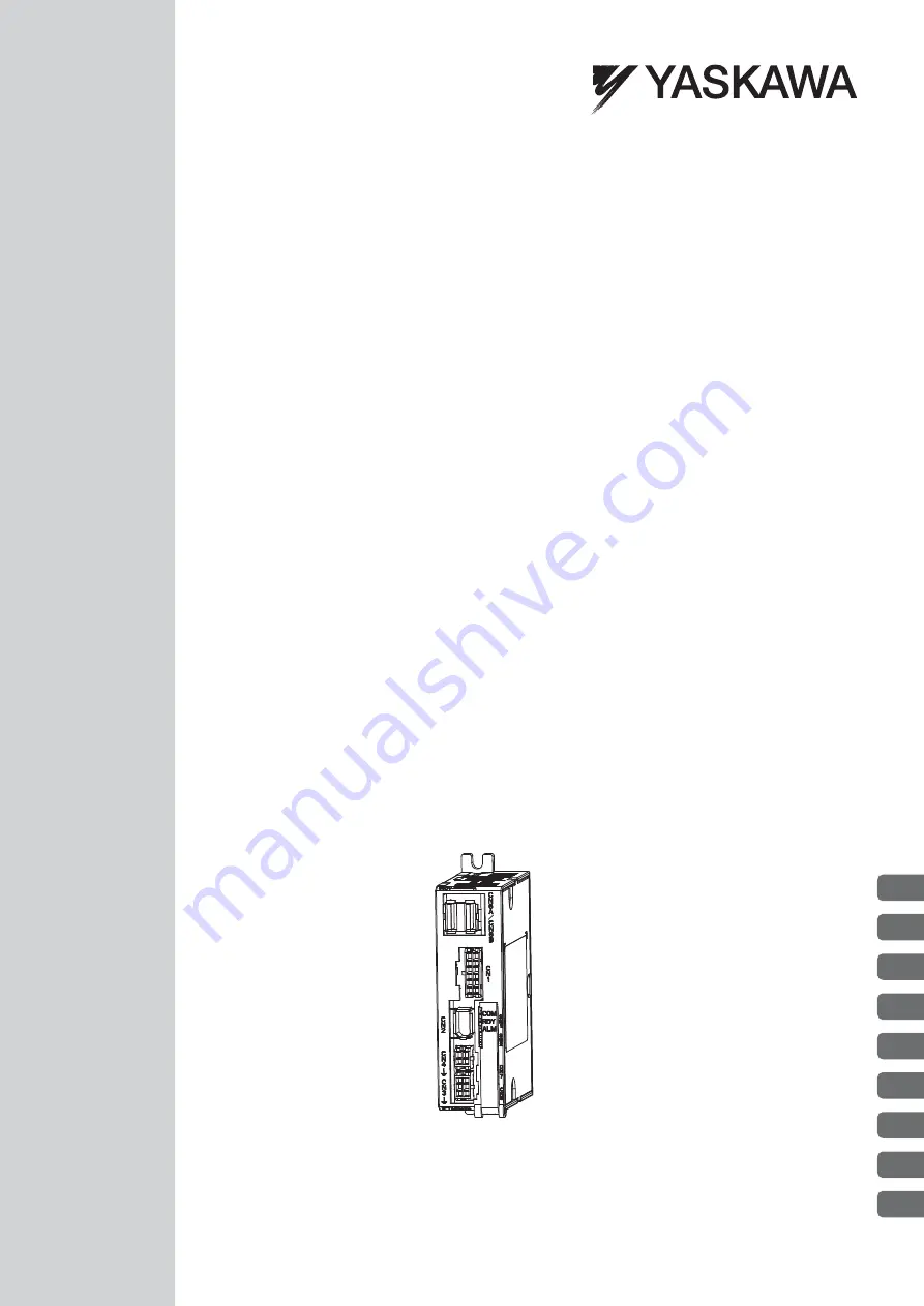
background image

SGMMV Servomotor
SGDV SERVOPACK

Rotational Motor

MECHATROLINK-

II

 Communications Reference

DC Power Input 

Σ

-

V

 Series

AC Servo Drives

USER'S MANUAL 

Design and Maintenance

MANUAL NO.   SIEP S800000 82A

1

2

3

4

5

6

7

8

9

Outline

S

Wiring and Connection

Operation

Adjustments

Utility Functions (Fn

†††

)

Monitor Displays (Un

†††

)

Troubleshooting

Appendix

Summary of Contents for E-V Series

Page 1: ...unications Reference DC Power Input Σ V Series AC Servo Drives USER S MANUAL Design and Maintenance MANUAL NO SIEP S800000 82A 1 2 3 4 5 6 7 8 9 Outline SigmaWin Wiring and Connection Operation Adjustments Utility Functions Fn Monitor Displays Un Troubleshooting Appendix ...

Page 2: ... liability is assumed with respect to the use of the information contained herein Moreover because Yaskawa is con stantly striving to improve its high quality products the information contained in this manual is subject to change without notice Every precaution has been taken in the preparation of this manual Nevertheless Yaskawa assumes no responsibility for errors or omissions Neither is any lia...

Page 3: ...including a servomotor and SERVOPACK i e a servo amplifier Servo System A servo control system that includes the combination of a servo drive with a host controller and peripheral devices M II Model MECHATROLINK II communications reference used for SERVOPACK interface Servo ON Power to motor ON Servo OFF Power to motor OFF Base Block BB Power supply to motor is turned OFF by shutting off the base ...

Page 4: ...a change to the parameter will be effective Indicates the parameter classification Indicates the minimum setting unit for the parameter Torque Position Speed Indicates the setting range for the parameter The notation n indicates a parameter for selecting functions Each corresponds to the setting value of that digit The notation shown here means that the third digit is 1 This section explains the s...

Page 5: ...pection DC Power Input Σ V Series User s Manual Setup Rotational Motor No SIEP S800000 80 Σ V Series Product Catalog No KAEP S800000 42 DC Power Input Σ V Series User s Manual Design and Maintenance Rotational Motor MECHATROLINK II Communications Reference this manual Σ V Series User s Manual MECHATROLINK II Commands No SIEP S800000 54 DC Power Input Σ V Series AC SERVOPACK SGDV Safety Precautions...

Page 6: ...ssibly result in loss of life or serious injury Indicates precautions that if not heeded could result in relatively serious or minor injury damage to the product or faulty operation In some situations the precautions indicated could have serious consequences if not heeded Indicates prohibited actions that must not be performed For example this symbol would be used to indicate that fire is prohibit...

Page 7: ...rect If Fn013 is executed when an incorrect value is set in Pn205 an incorrect value will be set in the encoder The alarm will disappear even if an incorrect value is set but incorrect positions will be detected resulting in a dangerous situation where the machine will move to unexpected positions Do not remove the cables or connectors from the SERVOPACK while the power is ON Failure to observe th...

Page 8: ...th ods other than fumigation must be used Example Heat treatment where materials are kiln dried to a core temperature of 56 C for 30 minutes or more If the electronic products which include stand alone products and products installed in machines are packed with fumigated wooden materials the electrical components may be greatly damaged by the gases or fumes resulting from the fumigation process In...

Page 9: ...sure that the polarity of the input power supply is correct Incorrect polarity may cause damage Always use the specified power supply voltage An incorrect voltage may result in fire or malfunction Take appropriate measures to ensure that the input power supply is supplied within the specified voltage fluctuation range An incorrect power supply may result in damage to the equipment Install external...

Page 10: ...ne hour should be allowed between the power being turned ON and OFF once actual operation has been started When carrying out JOG operation Fn002 origin search Fn003 or EasyFFT Fn206 forcing movable machine parts to stop does not work for forward overtravel or reverse overtravel Take necessary precautions Failure to observe this caution may result in damage to the equipment When using the servomoto...

Page 11: ...may result in damage to the equipment CAUTION When disposing of the products treat them as ordinary industrial waste Observe the following general precautions to ensure safe application The products shown in illustrations in this manual are sometimes shown without covers or protective guards Always replace the cover or protective guard as specified first and then operate the products in accordance...

Page 12: ...d product in a manner in which it was not originally intended 5 Causes that were not foreseeable with the scientific and technological understanding at the time of ship ment from Yaskawa 6 Events for which Yaskawa is not responsible such as natural or human made disasters 2 Limitations of Liability 1 Yaskawa shall in no event be responsible for any damage or loss of opportunity to the customer tha...

Page 13: ... property Systems that require a high degree of reliability such as systems that supply gas water or electricity or systems that operate continuously 24 hours a day Other systems that require a similar high degree of safety 4 Never use the product for an application involving serious risk to life or property without first ensuring that the system is designed to secure the required level of safety ...

Page 14: ...V UL1004 Model European Directives Harmonized Standards SERVOPACK SGDV EMC Directive 2004 108 EC EN 55011 group 1 class A EN 61000 6 2 EN 61800 3 Low Voltage Directive 2006 95 EC EN 61800 5 1 Servomotor SGMMV EMC Directive 2004 108 EC EN 55011 group 1 class A EN 61000 6 2 EN 61800 3 Low Voltage Directive 2006 95 EC EN 60034 1 EN 60034 5 ...

Page 15: ...in 2 3 2 5 Parameters Pn 2 5 2 5 1 Parameter Classification 2 5 2 5 2 Notation for Parameters 2 5 2 5 3 Setting Parameters 2 6 Chapter 3 Wiring and Connection 3 1 3 1 Main Circuit Wiring 3 2 3 1 1 Main Circuit Terminals CN3 CN4 3 2 3 1 2 Main Circuit Wires 3 3 3 1 3 Typical Main Circuit Wiring Examples 3 4 3 1 4 Power Supply Capacities and Power Losses 3 5 3 1 5 Input Power Supply Molded case Circ...

Page 16: ...Responses 4 23 4 5 3 Limitations 4 24 4 6 Limiting Torque 4 25 4 6 1 Internal Torque Limit 4 25 4 6 2 External Torque Limit 4 26 4 6 3 Checking Output Torque Limiting during Operation 4 27 4 7 Absolute Encoders 4 28 4 7 1 Connecting the Absolute Encoder 4 28 4 7 2 Absolute Data Request SENS ON Command 4 29 4 7 3 Battery Replacement 4 30 4 7 4 Absolute Encoder Setup 4 32 4 7 5 Multiturn Limit Setti...

Page 17: ...5 65 5 7 3 Related Parameters 5 70 5 8 Additional Adjustment Function 5 71 5 8 1 Switching Gain Settings 5 71 5 8 2 Manual Adjustment of Friction Compensation 5 75 5 8 3 Current Control Mode Selection Function 5 77 5 8 4 Current Gain Level Setting 5 77 5 8 5 Speed Detection Method Selection 5 77 5 8 6 Backlash Compensation Function 5 78 5 9 Compatible Adjustment Function 5 84 5 9 1 Feedforward Ref...

Page 18: ...nitor 7 6 7 2 5 Output Signal Monitor 7 7 Chapter 8 Troubleshooting 8 1 8 1 Alarm Displays 8 2 8 1 1 List of Alarms 8 2 8 1 2 Troubleshooting of Alarms 8 5 8 2 Warning Displays 8 15 8 2 1 List of Warnings 8 15 8 2 2 Troubleshooting of Warnings 8 16 8 3 Monitoring Communication Data on Occurrence of an Alarm or Warning 8 19 8 4 Troubleshooting Malfunction Based on Operation and Conditions of the Se...

Page 19: ...1 3 1 3 1 Ratings 1 3 1 3 2 Basic Specifications 1 4 1 3 3 MECHATROLINK II Function Specifications 1 6 1 4 SERVOPACK Internal Block Diagrams 1 7 1 4 1 MECHATROLINK II Communications Reference Model SGDV E11A 1 7 1 5 Examples of Servo System Configurations 1 8 1 6 SERVOPACK Model Designation 1 9 1 7 Inspection and Maintenance 1 10 ...

Page 20: ...or for encoder Connects the encoder in the servomotor CN4 Connector for servomotor Connects the main circuit cable for servomotor CN3 Connector for power supply Used for main circuit or control power supply input CN1 Connector for I O signal Used for reference input signals and sequence I O signals CN7 Connector for personal computer USB connector Communicates with a personal computer Use the conn...

Page 21: ... using a 24 VDC input the torque motor speed characteristics of the servomotor will be less than the characteristics of a 48 VDC input For details refer to Torque Motor Speed Characteristics of the SGMMV servomotor in Σ V Series Product Catalog Catalog No KAEP S800000 42 SGDV 1R7 2R9 Continuous Output Current Arms 1 7 2 9 Instantaneous Max Output Current Arms 4 1 8 6 Main Circuit Power Supply 24 V...

Page 22: ... oil or chemicals Free of dust salts or iron dust Pollution Degree 2 Altitude 1000 m or less Others Free of static electricity strong electromagnetic fields magnetic fields or exposure to radioactivity Harmonized Standards UL508C EN 55011 group 1 class A EN 61000 6 2 EN 61800 3 EN 61800 5 1 Mounting Base mounted Perfor mance Speed Control Range 1 5000 The lower limit of the speed control range mus...

Page 23: ...limit detection CLT Speed limit detection VLT Brake BK Warning WARN Near NEAR Signal allocations can be performed and positive and negative logic can be changed Communi cations Function Personal Computer Communications USB Supports SigmaWin Based on the USB 1 1 standard 12 Mbps LED Display ALM red RDY green COM green MECHATROLINK II Communications Setting Switches DIP Switch SW1 SW2 Number of pins...

Page 24: ...the combination of the DIP switch SW1 SW2 Baud Rate 10 Mbps 4 Mbps Can be selected by the DIP switch SW2 Transmission Cycle 250 μs 0 5 ms to 4 0 ms Multiples of 0 5 ms Can be selected by the DIP switch SW2 Number of Transmission Bytes 17 bytes per station or 32 bytes per station Can be selected by the DIP switch SW2 Reference Method Control Method Position speed or torque control with MECHATROLINK...

Page 25: ...4 U V W CN3 ALM RDY COM ENC CN2 5 V 12 5 V CN5 I O I F CN1 CN6A CN6B MECHATROLINK II communications Control power supply Main circuit power supply DC DC converter non isolated DC DC converter non isolated Voltage sensor Current sensor Gate drive overcurrent protector External monitor Personal computer ASIC PWM control etc CPU Position speed calculation etc Servomotor I O signal M II ...

Page 26: ...e for power supply SGMMV Servomotor 100 200 VAC Power supply Single phase 100 200 VAC Noise filter Molded case circuit breaker MCCB Protects the power line by shutting the circuit OFF when overcurrent is detected Eliminates external noise from the power line Magnetic contactor Turns the servo ON and OFF Install a surge absorber Brake power supply Used for a servomotor with a brake Encoder cable Ba...

Page 27: ...Specifications Code Interface S1 Analog voltage reference rotational servomotor P1 Pulse train reference rotational servomotor 11 MECHATROLINK II communications reference rotational servomotor 21 MECHATROLINK III communications reference rotational servomotor 11th 12th digits Software Specification Code Specification 00 Standard 7th digit Design Revision Order 1st 2nd 3rd digits 4th digit 5th 6th ...

Page 28: ...ced or not Note If the above operating conditions are not used replacement may be required sooner than the standard replacement period To extend the life of the parts reduce the ambient temperature Contact your Yaskawa representative if you require more detailed information Item Frequency Procedure Comments Exterior At least once a year Check for dust dirt and oil on the surfaces Clean with compre...

Page 29: ...Win 2 2 2 2 Preparing SigmaWin 2 2 2 3 Connecting a PC with SigmaWin 2 2 2 4 Starting and Operating the SigmaWin 2 3 2 5 Parameters Pn 2 5 2 5 1 Parameter Classification 2 5 2 5 2 Notation for Parameters 2 5 2 5 3 Setting Parameters 2 6 ...

Page 30: ...nline Manual To view the online manual use the following procedure 1 Turn on the computer 2 Double click YE_Applications icon 3 Double click MANUAL icon 4 Double click SigmaWin English Edition Online Manual Connection Method Description Conventional Use a communications cable to connect one PC with SigmaWin installed to one SERVOPACK To use SigmaWin with a different SERVOPACK disconnect the cable ...

Page 31: ...vo System Configurations 2 Turn on the SERVOPACK 3 Turn on the computer 4 Double click the YE_Applications icon 5 Double click the SigmaWin English Edition icon The SigmaWin startup window will appear When the startup of SigmaWin has been completed the Connect window will appear 6 Click Search The Search Condition Setting box will appear Note Use the offline mode when running SigmaWin without conn...

Page 32: ...VOPACK not found is shown refer to the online manual To view the online manual refer to 2 3 Connecting a PC with SigmaWin 9 Select the SERVOPACK to be connected 10 Click Connect The SigmaWin main window will appear Note For details on how to operate SigmaWin refer to the online manual for SigmaWin Refer to 2 3 Connecting a PC with SigmaWin for the procedure to access the Online Manual MECHA ...

Page 33: ...t each parameter individu ally Tuning Parameters Parameters for tuning con trol gain and other parame ters Set Pn00B 0 to 1 There is no need to set each parameter individually Pn406 Emergency Stop Torque Setting Range 0 to 800 1 800 After change Setting Unit Factory Setting When Enabled Classification Setup Parameter number Position Torque The control methods for which the parameters applies Speed...

Page 34: ...e Online Parameter Editing dialog box These methods are described below 1 Using the Parameter Editing Dialog Box 1 In the SigmaWin main window click Parameters Edit Parameters The Parameter Editing dialog box will appear 2 Select a parameter to edit If the parameter cannot be seen in the Parameter Editing dialog box click the arrows to view the param eter MECH A MECH A ...

Page 35: ... to be set For parameters for selecting functions Click the arrow to open the setting list for each digit and select one item in each list 5 Click OK 6 Click Write The new parameter settings will be saved in the SERVOPACK This completes the editing of the parameter If the following window appears go to step 7 7 Click OK 8 To enable the change in the setting restart the SERVOPACK MECHA ...

Page 36: ... dialog box will appears 2 Click Setup The Set Parameters box will appear Values edited in the Online Parameter Editing dialog box are immediately changed in the SERVOPACK If the power to the SERVOPACK is turned OFF or the communication between the SERVOPACK and the SigmaWin is interrupted while editing parameters online the edited values will not be saved in the SERVOPACK MECHA MECHA ...

Page 37: ...eter to edit and then click OK The Set Parameters box will appear again 5 Click OK The Online Parameter Editing dialog box will appear again 6 Click the setting arrows to change the value of the setting If an allowable range is specified set the value within that range The value of the parameter in the SERVOPACK will immediately change to the new value MECHA ...

Page 38: ...8 3 2 1 I O Signal CN1 Names and Functions 3 8 3 2 2 Example of I O Signal Connections 3 9 3 3 I O Signal Allocations 3 10 3 3 1 Input Signal Allocations 3 10 3 3 2 Output Signal Allocations 3 16 3 4 Examples of Connection to Host Controller 3 20 3 4 1 Sequence Input Circuit 3 20 3 4 2 Sequence Output Circuit 3 21 3 5 Wiring MECHATROLINK II Communications 3 22 3 6 Encoder Connection 3 23 3 6 1 Enc...

Page 39: ...umber Name Specification CN3 L1 6 Main circuit power input terminal 24 VDC 15 or 48 VDC 15 L2 3 Main circuit power input terminal C1 5 Control power input terminal 24 VDC 15 C2 4 Control power input terminal 1 2 Ground terminals Use for connecting the power supply ground terminal CN4 U 1 Servomotor connection terminal phase U Use for connecting to the servomotor V 2 Servomotor connection terminal ...

Page 40: ...uction of the allowable current Use a heat resistant wire under high surrounding air or panel temperatures The length of cables for power supply is 10 m max and the length of cables for ser vomotor main circuit is 50 m max Cable SERVOPACK Model SGDV Remarks 1R7E 2R9E CN3 for power supply Connector 43025 0600 Made by Molex Japan Co Ltd 6 poles Contact 43030 0001 Made by Molex Japan Co Ltd For main ...

Page 41: ...arate AC DC power supplies for the main circuits and for controls Power supplies must have double or reinforced insulation that conforms to safety standards Do not connect devices such as motors or solenoids that greatly change the load or devices such as electromagnetic switches that generate surge voltages to the con troller power line Failure to observe this caution may result in deterioration ...

Page 42: ...d case circuit breakers and fuses that meet the following cutoff characteristics Cutoff characteristics 25 C 300 of the rated load input current five seconds min Does not cut off at the inrush current value of the power supply 1 Values with instantaneous maximum load 2 Values with rated load Main Circuit Power Supply Maximum Applicable Servomotor Capacity W SERVOPACK Model SGDV Power Supply Capaci...

Page 43: ...SERVOPACK with a DC power input If the alarm outputs from the SERVOPACKs are connected in series it will not be possible to receive the output signals normally when an alarm occurs R T 1QF 1FLT 1KM 1PL 1Ry 2Ry 3Ry 1Ry 2Ry 3Ry 1KM 1KM 1SA CN3 L1 L2 C1 C2 CN1 4 5 COM_SG ALM 1Ry 1D 0V 24V M CN3 L1 L2 C1 C2 CN1 4 5 COM_SG ALM 2Ry 2D 0V 24V M CN3 L1 L2 C1 C2 CN1 4 5 COM_SG ALM 3Ry 3D 0V 24V M 1QF 1FLT ...

Page 44: ...e sure to ground at only one point Ground the servomotor directly if the servomotor is insulated from the machine The signal cable conductors are as thin as 0 2 mm2 or 0 3 mm2 Do not impose excessive bending force or tension Always use a molded case circuit breaker 1QF or a fuse to protect the servo system from intersystem faults Install a ground fault detector The SERVOPACK does not have a built ...

Page 45: ... 8 Forward run prohibited Reverse run prohibited With overtravel prevention Stops servomotor when movable part travels beyond the allowable range of motion 4 3 1 EXT 1 Can be allocated External latch signal 1 Connects the external signals that latch the current feedback pulse counter Note To use this signal allocate it to CN1 7 24VIN 2 Control power supply for sequence signal Control power supply ...

Page 46: ...als SO1 SO2 and SO3 can be changed by using the parameters Refer to 3 3 1 Input Signal Allocations and 3 3 2 Output Signal Allocations BK SO1 SO2 SO3 ALM 11 10 4 24VIN 24V 3 3 kΩ 2 8 7 P OT N OT DEC 3 COM_SG FG 9 5 1 CN1 SERVOPACK Photocoupler output Max operating voltage 30 VDC Max output current 50 mA DC Servo alarm output OFF for an alarm Brake Brake released when ON Reverse run prohibited Proh...

Page 47: ...ignals resulting in an unexpected machine operation Input Signal Names and Parameters Validity Level Input Signal CN1 Pin Numbers Connection Not Required SERVOPACK judges the connection 7 3 8 Always ON Always OFF Forward Run Prohibited Pn50A 3 H P OT 0 1 2 to 6 7 8 L P OT 9 A B to F Reverse Run Prohibited Pn50B 0 H N OT 0 1 2 to 6 7 8 L N OT 9 A B to F Forward External Torque Limit Pn50B 2 L P CL ...

Page 48: ...81 to n 8881 Pn50B is changed from n 8882 to n 8182 1 In the SigmaWin main window click Parameters Edit Parameters The Parameter Editing dialog box will appear Reserve External Torque Limit Pn50B 3 L N CL 0 1 2 to 6 7 8 H N CL 9 A B to F Homing Deceleration LS Pn511 0 L DEC 0 1 2 to 6 7 8 H DEC 9 A B to F External Latch Signal 1 Pn511 1 L EXT1 0 to 6 7 8 H EXT1 9 to F Input Signal Names and Parame...

Page 49: ...ion 3 3 1 Input Signal Allocations 3 12 2 Select Pn50A If Pn50A cannot be seen in the Parameter Editing dialog box click the arrows button to view the parameter 3 Click Edit The Edit box for Pn50A will appear MEC HA MEC HA ...

Page 50: ...lect 8 Forward run allowed in the P OT Signal Mapping list 5 Click OK The Edit box will close and Parameter Editing dialog box will appear again 6 Select Pn50B If Pn50B cannot be seen in the Parameter Editing dialog box click the arrows button to view the parameter MEC HA MEC HA ...

Page 51: ...d Connection 3 3 1 Input Signal Allocations 3 14 7 Click Edit The Edit box for Pn50B will appear 8 For the 2nd digit select 1 ON when CN1 3 input signal is ON L level in the P CL Signal Mapping list MEC HA MEC HA ...

Page 52: ...Edit box will close and the Parameter Editing dialog box will appear again 10 Click Write The following window will appear after the new parameter setting has been saved in the SERVOPACK 11 Click OK 12 To enable the change in the setting restart the SERVOPACK MEC HA MEC HA ...

Page 53: ...o the same output circuit a signal is output with OR logic circuit Output Signal Names and Parameters Output Signal CN1 Pin Numbers Invalid not use 11 10 9 Positioning Completion Pn50E 0 COIN 1 2 3 0 Speed Coincidence Detection Pn50E 1 V CMP 1 2 3 0 Rotation Detection Pn50E 2 TGON 1 2 3 0 Servo Ready Pn50E 3 S RDY 1 2 3 0 Torque Limit Detection Pn50F 0 CLT 1 2 3 0 Speed Limit Detection Pn50F 1 VLT...

Page 54: ...ons The procedure to set the position completion signal COIN that was previously disabled is allocated to CN1 10 is shown below Parameter Changes Pn50E is changed from n 0000 to n 0002 1 In the SigmaWin main window click Parameters Edit Parameters The Parameter Editing dialog box will appear MEC HA ...

Page 55: ...on 3 3 2 Output Signal Allocations 3 18 2 Select Pn50E If Pn50E cannot be seen in the Parameter Editing dialog box click the arrows button to view the param eter 3 Click Edit The Edit box for Pn50E will appear MEC HA MEC HA ...

Page 56: ...the Positioning Completion Signal Mapping COIN list 5 Click OK The Edit box will close and the Parameter Editing dialog box will appear again 6 Click Write The following window will appear after the new parameter setting has been saved in the SERVOPACK 7 Click OK 8 To enable the change in the setting restart the SERVOPACK MEC HA MEC HA ...

Page 57: ...e 50 mA minimum The SERVOPACK s input circuit uses bidirectional photocoupler Select either the sink circuit or the source circuit according to the specifications required for each machine Note The connection example in 3 2 2 shows sink circuits The ON OFF polarity differs between when a sink circuit is connected and when a source circuit is connected Relay Circuit Example Open collector Circuit E...

Page 58: ...ine receiver circuit Note The maximum allowable voltage and the allowable range of current capacity for photocoupler output circuits are as follows Voltage 30 VDC Current 5 to 50 mA DC Incorrect wiring or incorrect voltage application to the output circuit may cause short cir cuit If a short circuit occurs as a result of any of these causes the holding brake will not work This could damage the mac...

Page 59: ...le between stations L1 L2 Ln must be 0 5 m or more 2 The total cable length must be L1 L2 Ln 50 m 3 When multiple SERVOPACKs are connected by MECHATROLINK II communications cable a terminator must be installed at the final SERVOPACK Ln L1 L2 Terminator DC24V DC 0V MP2300 YASKAWA TEST ޓ ޓ ޓ Option Option RDY ALM TX RUN ERR BAT MON CNFG INT SUP STOP SW1 OFF ON BATTERY CPU I O M I II 218IF 01 ERR COL...

Page 60: ...to connect these pins to the SERVOPACK 3 6 2 Encoder Connection Examples The following diagrams show connection examples of the encoder and the SERVOPACK 1 Using as an Incremental Encoder represents shielded twisted pair wires Signal Name Pin No Function PG 5 V 1 Encoder power supply 5 V PG 0 V 2 Encoder power supply 0 V BAT 3 Battery BAT 4 Battery PS 5 Serial data PS 6 Serial data Shield Shell 1 ...

Page 61: ...nts shielded twisted pair wires 2 When using an absolute encoder provide power by installing an encoder cable with a JUSP BA01 E Battery Case ENC 3 4 CN2 1 5 6 1 2 PG5 V PG0 V PS PS BAT BAT 2 2 Battery Absolute encoder Shell Connector shell Output line driver SN75ALS174 or the equivalent SERVOPACK MECHA ...

Page 62: ... cables in the same duct Keep the servomotor main circuit cables separated from the I O signal cables and encoder cables by at least 30 cm Do not share the power supply with an electric welder or electrical discharge machine When the SERVO PACK is placed near a high frequency generator install a noise filter on the input side of the power supply cables As for the wiring of noise filter refer to 1 ...

Page 63: ...ground the ground terminal If the servomotor is grounded via the machine a switching noise current will flow from the SERVOPACK main circuit through servomotor stray capacitance The above grounding is required to prevent the adverse effects of switching noise Noise on the I O Signal Cable If the I O signal cable receives noise ground the 0 V line SG of the I O signal cable If the servomotor main c...

Page 64: ...e filter ground wire from the output lines Do not accommodate the noise filter ground wire output lines and other signal lines in the same duct or bundle them together Some noise filters have large leakage currents The grounding measures taken also affects the extent of the leakage current If necessary select an appropriate leakage cur rent detector or leakage current breaker taking into account t...

Page 65: ...er is located inside a control panel first connect the noise filter ground wire and the ground wires from other devices inside the control panel to the ground plate for the control panel then ground the plates Shielded ground wire Noise Filter Noise Filter SERVOPACK SERVOPACK SERVOPACK SERVOPACK Ground plate Ground plate Incorrect Correct AC DC converter Noise Filter Control Panel Ground SERVOPACK...

Page 66: ...ial Operation 4 18 4 4 2 Trial Operation via MECHATROLINK II 4 19 4 4 3 Electronic Gear 4 20 4 5 Test Without Motor Function 4 22 4 5 1 Motor Information 4 22 4 5 2 Motor Position and Speed Responses 4 23 4 5 3 Limitations 4 24 4 6 Limiting Torque 4 25 4 6 1 Internal Torque Limit 4 25 4 6 2 External Torque Limit 4 26 4 6 3 Checking Output Torque Limiting during Operation 4 27 4 7 Absolute Encoders...

Page 67: ...tput Signal WARN 4 40 4 8 3 Rotation Detection Output Signal TGON 4 41 4 8 4 Servo Ready Output Signal S RDY 4 41 4 8 5 Speed Coincidence Output Signal V CMP 4 42 4 8 6 Positioning Completed Output Signal COIN 4 43 4 8 7 Positioning Near Output Signal NEAR 4 44 4 8 8 Speed Limit Detection Signal VLT 4 44 ...

Page 68: ...IP switch SW2 OFF ON SW1 factory settings 1 2 3 4 OFF ON SW2 factory settings 1 2 3 4 M II SW2 Function Setting Description Factory setting Pin 1 Sets the baud rate OFF 4 Mbps MECHATROLINK I ON ON 10 Mbps MECHATROLINK II Pin 2 Sets the number of transmission bytes OFF 17 bytes ON ON 32 bytes Pin 3 Sets the station address OFF Station address 40H SW1 OFF ON Station address 50H SW1 Pin 4 Reserved Do...

Page 69: ...ON OFF OFF 42H OFF ON ON OFF OFF 43H OFF OFF OFF ON OFF 44H OFF ON OFF ON OFF 45H OFF OFF ON ON OFF 46H OFF ON ON ON OFF 47H OFF OFF OFF OFF ON 48H OFF ON OFF OFF ON 49H OFF OFF ON OFF ON 4AH OFF ON ON OFF ON 4BH OFF OFF OFF ON ON 4CH OFF ON OFF ON ON 4DH OFF OFF ON ON ON 4EH OFF ON ON ON ON 4FH ON OFF OFF OFF OFF 50H ON ON OFF OFF OFF 51H ON OFF ON OFF OFF 52H ON ON ON OFF OFF 53H ON OFF OFF ON O...

Page 70: ...ference The standard setting for forward rotation is counterclockwise CCW as viewed from the load end of the ser vomotor Note SigmaWin trace waveforms are shown in the above table Parameter Forward Reverse Reference Direction of Motor Rotation Applicable Overtravel OT Pn000 n 0 Sets CCW as forward direction Factory setting Forward Reference P OT Reverse Reference N OT n 1 Sets CW as forward direct...

Page 71: ...ical axes Occurrence of overtravel may cause a workpiece to fall because the BK signal is on that is when the brake is released Set the parameter Pn001 n 1 to bring the servomotor to zero clamp state after stopping to prevent a workpiece from falling Other axes to which external force is applied Overtravel will bring about a baseblock state after the servomotor stops which may cause the servomotor...

Page 72: ...tained after the ser vomotor coasts to a stop For details on servomotor stopping methods after the SV_OFF command is received or an alarm occurs refer to 4 3 5 Stopping Servomotors after SV_OFF Command or Alarm Occurrence When Servomotor Stopping Method is Set to Decelerate to Stop Emergency stop torque can be set with Pn406 The setting unit is a percentage of the rated torque The factory setting ...

Page 73: ...this method during an overtravel state the occurrence of the warning will not be indicated until the overtravelling is corrected and reset The overtravel warning will be detected when the software limit is in effect Related Parameter CAUTION The overtravel warning function only detects warnings It does not affect on stopping for overtravel or motion operations at the host controller The next step ...

Page 74: ...n the input target position exceeds the software limit a deceleration stop will be performed from the software limit set position 3 Software Limit Setting Set software limits value in the forward and reverse directions Because the limit zone is set according to the forward or reverse direction the reverse limit must be less than the forward limit Parameter Description When Enabled Classification P...

Page 75: ...from the host controller to the SERVOPACK 3 Use Pn506 Pn507 and Pn508 to set the timing of when the brake will be activated and when the servomotor power will be turned OFF The brake built into the servomotor with brakes is a de energization brake which is used only to hold and cannot be used for braking Use the holding brake only to hold a stopped servomotor Model Voltage Brake Release Time ms Br...

Page 76: ...holding brake by the emergency stop The allocation of the BK signal can be changed Refer to 3 Brake Signal BK Allo cation to set the parameter Pn50F Always separate the 24 VDC power supply for the 24 V brake from other power sup plies such as the control or I O signal CN1 power supplies If the power supply is shared the I O signals might malfunction M BK ENC U V W 5 11 CN2 BK RY BK RY 24V L1 L2 C1...

Page 77: ...g Output BK CN1 11 ON closed Releases the brake OFF open Applies the brake The BK signal is still ON during overtravel and the brake is still released Parameter Connector Pin Number Meaning When Enabled Classifica tion Pn50F n 0 The BK signal is not used After restart Setup n 1 Factory setting CN1 11 The BK signal is output from output termi nal CN1 11 n 2 CN1 10 The BK signal is output from outpu...

Page 78: ...g the servomotor to control a vertical axis the machine movable part may shift slightly depending on the brake ON timing due to gravity or an external force To eliminate this slight shift set parameter so that the power to the servomotor turns OFF after the brake is applied This parameter changes the brake ON timing while the servomotor is stopped SV_OFF command BK output Power to motor Brake rele...

Page 79: ...ing Unit Factory Setting When Enabled 10 to 100 10 ms 50 Immediately Setup Speed Position Torque Speed Position Torque BK Signal Output Conditions When Servomotor Rotating The BK signal goes to high level brake ON when either of the fol lowing conditions is satisfied When the motor speed falls below the level set in Pn507 after the power to the servomo tor is turned OFF When the time set in Pn508 ...

Page 80: ...orate if turning the power supply ON and OFF or starting and stopping the servomotor during the servo ON status while there is a reference input Use a speed reference or position reference to start and stop the servomotor If turning OFF the main circuit power supply or the control power supply during opera tion without turning OFF the servo the servomotor will coast to a stop In this case the stop...

Page 81: ...Pn52B This protective function enables the warning out put signal WARN to serve as a protective function and to be output at the best timing for your system The following graph shows an example of the detection of an overload warning when the overload warning level Pn52B is changed from 20 to 50 An overload warning is detected in half of the time required to detect an overload alarm Note For detai...

Page 82: ...arlier Changing the setting of Pn52C will change the detection timing of the overload alarm so the time required to detect the overload warning will also be changed As a guideline of motor heating conditions the relationship between the heat sink sizes and deratings of base current is shown in a graph in Servomotor Heating Conditions in Rotary Servomotors General Instruction in Σ V Series Product ...

Page 83: ...asures before performing trial operation if any problem exists Are all wiring and connections correct Are all nuts and bolts securely tightened Note When performing trial operation on a servomotor that has been stored for a long period of time perform the inspec tion according to the procedures described in AC Servomotor Safety Precautions Manual No TOBP C230200 00 2 SERVOPACKs Inspect and check t...

Page 84: ...Overtravel 4 4 3 Electronic Gear 4 3 2 Overtravel 4 3 2 Overtravel 6 Save these settings step 5 If saving the settings in the controller use the PRM_WR command If saving the settings in the SERVOPACK use the PPRM_WR com mand Σ V Series User s Manual MECHATROLINK II Commands Manual No SIEP S800000 54 7 Send the SV_ON command A reply showing that the servomotor has switched to Drive status and that ...

Page 85: ...tion 17 bit 131072 1 2 3 The section indicates the difference between using and not using an electronic gear when a workpiece is moved 10 mm in the following configuration Calculate the required reference units 131072 reference units is 1 revolution Therefore 10 6 131072 218453 33 reference units Input 218453 references as reference units Reference units must be calculated per reference complicate...

Page 86: ...atio B A 4000 If the electronic gear ratio is outside this range a parameter setting error 1 A 040 will be output Symbol Specification Encoder Resolutions SGMMV 2 17 bit absolute 131072 Step Operation Load Configuration Ball Screw Disc Table Belt and Pulley 1 Check machine specifica tions Ball screw pitch 6 mm Gear ratio 1 1 Rotation angle per revolu tion 360 Gear ratio 1 100 Pulley diameter 100 m...

Page 87: ... encoder informa tion The set values of Pn00C 1 and Pn00C 2 are not used 2 Motor Not Connected The virtual motor information that is stored in the SERVOPACK is used The set values of Pn00C 1 and Pn00C 2 are used for the encoder information Encoder Resolution The encoder information for the motor is set in Pn00C 1 Encoder Type The encoder information for the motor is set in Pn00C 2 Parameter Meanin...

Page 88: ...e test without a motor the following responses are simulated for references from the host controller according to the gain settings for position or speed control Servomotor position Servomotor speed However the load model will be a rigid system with the moment of inertia ratio that is set in Pn103 ...

Page 89: ...arm reset Fn00C Offset adjustment of analog monitor output Fn00D Gain adjustment of analog monitor output Fn00E Automatic offset signal adjustment of the motor current detection signal Fn00F Manual offset signal adjustment of the motor current detection signal Fn010 Write prohibited setting Fn011 Servomotor model display Fn012 Software version display Fn013 Multiturn limit value setting change whe...

Page 90: ... Description Reference Section Internal torque limit Always limits torque by setting the parameter 4 6 1 External torque limit Limits torque by input signal from the host controller 4 6 2 Torque limit with P_TLIM N_TLIM commands Limits torque by using the P_TLIM and N_TLIM commands Torque limit with P_CL N_CL signals of OPTION Field and P_TLIM N_TLIM commands Combines torque limit methods by using...

Page 91: ...on of the servomotor Type Signal Name Connector Pin Number Setting Meaning Limit value Input P CL Must be allocated ON closed Forward external torque limit ON The smaller value of these set tings Pn402 or Pn404 OFF open Forward external torque limit OFF Pn402 Input N CL Must be allocated ON closed Reverse external torque limit ON The smaller value of these set tings Pn403 or Pn405 OFF open Reverse...

Page 92: ...llowing signal can be output to indicate that the servomotor output torque is being limited Note Use parameter Pn50F 0 to allocate the CLT signal for use For details refer to 3 3 2 Output Signal Allocations P CL OFF ON N CL OFF ON Pn402 Pn403 0 Torque Speed Pn403 0 Pn404 Pn402 Torque Speed 0 Pn403 Pn405 Pn402 Torque Speed 0 Pn403 Pn405 Pn404 Pn402 Torque Speed Type Signal Name Connector Pin Number...

Page 93: ...g the absolute encoder as an incremental encoder 4 7 1 Connecting the Absolute Encoder The following diagram shows the connection between a servomotor with an absolute encoder the SERVO PACK and the host controller 1 represents shielded twisted pair wires 2 When using an absolute encoder provide power by installing an encoder cable with a JUSP BA01 E Battery Case or install a battery on the host c...

Page 94: ..._ON command is sent at the following timing Send the SENS_OFF command to turn OFF the control power supply 5 seconds max OFF OFF OFF OFF Approx 560 ms max The servomotor will not be turned ON even if the SV_ON command is received during this interval OFF OFF OFF OFF SERVOPACK control power supply ALM signal OFF Alarm status SENS_ON Turn Encoder Power Supply ON Servomotor power ON ON Normal status ...

Page 95: ...sec onds when the control power is turned ON No battery related alarm will be displayed even if the battery voltage drops below the specified value after these 4 seconds If Pn008 0 is set to 1 alarm detection will be always enabled after the ALM signal outputs max 5 seconds when the control power supply is turned ON Parameter Meaning When Enabled Classification Pn008 n 0 Factory setting Outputs th...

Page 96: ...attery turn OFF the control power supply to clear the absolute encoder battery error alarm A 830 6 Turn ON the control power supply again 7 Check that the alarm display has been cleared and that the SERVOPACK operates normally If the SERVOPACK control power supply is turned OFF and the battery is disconnected which includes disconnecting the encoder cable the absolute encoder data will be deleted ...

Page 97: ... write prohibited setting parameter Fn010 must be set to Write permitted P 0000 The servomotor power must be OFF 3 Operating Procedure Use the following procedure This setting can be performed using the adjustment command ADJ For details refer to Σ V Series User s Manual MECHATROLINK II Commands Manual No SIEP S800000 54 1 Make sure that the motor power is OFF 2 In the SigmaWin main window click S...

Page 98: ...m will change Click Cancel to return to the previous window without resetting the absolute encoder 5 Click Continue to set up the encoder If Setup is Unsuccessful If setting up is attempted with the servo ON a reset conditions error occurs and the processing is aborted Click OK to return to the main window If Setup Completes Normally If the encoder is set up successfully a warning message will app...

Page 99: ...4 Operation 4 7 4 Absolute Encoder Setup 4 34 6 Click OK to return to the main window 7 To perform an origin search restart the SERVOPACK ...

Page 100: ...ng Pn205 m 1 The case in which the relationship between the turntable revolutions and motor revolutions is m 100 and n 3 is shown in the following graph Pn205 is set to 99 Pn205 100 1 99 Note This parameter is valid when the absolute encoder is used The range of the data will vary when this parameter is set to anything other than the factory setting 1 When the motor rotates in the reverse directio...

Page 101: ...te permitted P 0000 2 Operating Procedure Use the following procedure This setting can be performed with the adjustment command ADJ For information the adjustment command ADJ refer to Σ V Series User s Manual MECHATROLINK II Commands Manual No SIEP S800000 54 1 In the SigmaWin main window click Setup Set Absolute Encoder Multi Turn Limit Setting A verification message will appear confirming if you...

Page 102: ...d number of revolutions 4 To save the settings click Writing into the Servopack A warning message will appear 5 Click OK and the settings are changed to the new ones 6 Restart the SERVOPACK Because only the settings for the SERVOPACK were made the settings for the servomotor are still incomplete and an alarm occurs MEC HA MEC HA MEC HA ...

Page 103: ...Multi Turn Limit Setting again A verification message will appear confirming if you want to continue although the position data will change 8 Click Continue The Multi Turn Limit Setting box will appear To change the settings click Re Change 9 To save the settings click Writing into the Motor A warning message will appear 10 Click OK MEC HA MEC HA MEC HA ...

Page 104: ...eived by MECHA TROLINK communications this parameter will be enabled Example If the encoder position X is set at the origin of the machine coordinate system 0 Pn808 X Pn808 Absolute Encoder Origin Offset Classification Setting Range Setting Unit Factory Setting When Enabled 1073741823 to 1073741823 1 reference unit 0 Immediately Setup Position Encoder position Origin Origin Machine coordinate syst...

Page 105: ... Manual No SIEP S800000 54 4 8 2 Warning Output Signal WARN This signal is for a warning issued before the occurrence of an alarm Refer to 8 2 1 List of Warnings Signal Specifications Note Use parameter Pn50F 3 to allocate the WARN signal for use For details refer to 3 3 2 Output Signal Alloca tions Configure an external circuit so that this alarm output turns OFF the main circuit power supply for...

Page 106: ...When an absolute encoder is used If an absolute encoder is used the output of absolute data to the host controller must have been completed when the SENS_ON command is received 1 Signal Specifications Note Use parameter Pn50E 3 to allocate the S RDY signal for use For details refer to 3 3 2 Output Signal Allocations Type Signal Name Connector Pin Number Setting Meaning Output TGON Must be allocate...

Page 107: ...ocations for details The V CMP signal is output when the difference between the reference speed and actual motor speed is below this setting Example The V CMP signal is output at 1900 to 2100 min 1 if the Pn503 is set to 100 and the reference speed is 2000 min 1 Type Signal Name Connector Pin Number Setting Meaning Output V CMP Must be allocated ON closed Speed coincides OFF open Speed does not co...

Page 108: ...put unexpectedly reduce the set value until it is no longer output If the position error is kept to a minimum when the positioning completed width is small use Pn207 3 to change output timing for the COIN signal Type Signal Name Connector Pin Number Setting Meaning Output COIN Must be allocated ON closed Positioning has been completed OFF open Positioning is not completed Pn522 Positioning Complet...

Page 109: ...r to protect the machine A servomotor in torque control is controlled to output the specified torque but the motor speed is not con trolled Therefore if an excessive reference torque is set for the load torque on the machinery side the speed of the servomotor may increase greatly If that may occur use this function to limit the speed Note The actual limit value of motor speed depends on the load c...

Page 110: ...nal speed limit function is selected in Pn002 1 the motor speed is controlled by the speed limit value VLIM For details refer to Σ V Series User s Manual MECHATROLINK II Commands Manual No SIEP S800000 54 Type Signal Name Connector Pin Number Setting Meaning Output VLT Must be allocated ON closed Servomotor speed limit being applied OFF open Servomotor speed limit not being applied Parameter Meani...

Page 111: ...dvanced Autotuning by Reference Fn202 5 34 5 4 1 Advanced Autotuning by Reference 5 34 5 4 2 Advanced Autotuning by Reference Procedure 5 36 5 4 3 Related Parameters 5 42 5 5 One parameter Tuning Fn203 5 43 5 5 1 One parameter Tuning 5 43 5 5 2 One parameter Tuning Procedure 5 43 5 5 3 One parameter Tuning Example 5 52 5 5 4 Related Parameters 5 53 5 6 Anti Resonance Control Adjustment Function Fn...

Page 112: ...5 8 3 Current Control Mode Selection Function 5 77 5 8 4 Current Gain Level Setting 5 77 5 8 5 Speed Detection Method Selection 5 77 5 8 6 Backlash Compensation Function 5 78 5 9 Compatible Adjustment Function 5 84 5 9 1 Feedforward Reference 5 84 5 9 2 Mode Switch P PI Switching 5 85 5 9 3 Torque Reference Filter 5 87 5 9 4 Position Integral 5 89 ...

Page 113: ...n is required to make adjust ments Utility Function for Adjustment Outline Applicable Control Method Tuning less Levels Setting Fn200 This function is enabled when the factory settings are used This function can be used to obtain a stable response regardless of the type of machine or changes in the load Speed and Position Advanced Autotuning Fn201 The following parameters are automatically adjuste...

Page 114: ...usts gains and filters with user reference inputs Adjust using One parameter Tuning Manually adjusts gains and filters Position loop gain speed loop gain filters and friction compensation adjustments are available Continuous vibration occurs Reduce the vibration using Anti resonance Control Adjustment Function Residual vibration occurs at positioning Reduce the vibration using Vibration Suppressio...

Page 115: ...hown below Measuring instrument is not included 2 Monitor Signal The shaded parts in the following diagram indicate analog output signals that can be monitored Line Color Signal Name Factory Setting White Analog monitor 1 Torque reference 1 V 100 rated torque Red Analog monitor 2 Motor speed 1 V 1000 min 1 Black 2 lines GND Analog monitor GND 0 V Probe GND Measuring probe Measuring probe Probe GND...

Page 116: ... rated torque n 03 Position error 0 05 V 1 reference unit 0 V at speed torque control n 04 Position amplifier error 0 05 V 1 encoder pulse unit Position error after electronic gear conversion n 05 Position reference speed 1 V 1000 min 1 n 06 n 07 Reserved Do not change n 08 Positioning completed Positioning completed 5 V Positioning not com pleted 0 V Completion indicated by out put voltage n 09 S...

Page 117: ...g monitor output voltage V When multiplier is set to 1 When multiplier is set to 10 Motor speed min 1 Motor speed min 1 Note Linear effective range within 8 V Output resolution 16 bit Pn550 Analog Monitor 1 Offset Voltage Classification Setting Range Setting Unit Factory Setting When Enabled 10000 to 10000 0 1 V 0 Immediately Setup Pn551 Analog Monitor 2 Offset Voltage Classification Setting Range...

Page 118: ...ulated from the position loop gain Pn102 and the motor speed with the follow ing equation Excessive Position Error Alarm Level Pn520 1 reference unit 1 Refer to 4 4 3 Electronic Gear 2 To check the Pn102 setting change the parameter display setting to display all parameters Pn00B 0 1 At the end of the equation a coefficient is shown as 1 2 to 2 This coefficient is used to add a margin that prevent...

Page 119: ...wer the servomotor will move and this movement will clear the counter of all position errors Because the servomotor will move sud denly and unexpectedly safety precautions are required To prevent the servomotor from moving suddenly select the appropriate level for the excessive position error alarm level at servo ON Pn526 to restrict opera tion of the servomotor Related Parameters Pn520 327680 2 6...

Page 120: ...er is turned ON when the position error is greater than the set value of Pn526 while the servomotor power is OFF A d02 Position Error Overflow Alarm by Speed Limit at Servo ON When the position errors remain in the error counter Pn529 limits the speed if the servomotor power is turned ON If Pn529 limits the speed in such a state this alarm occurs when position references are input and the number o...

Page 121: ...om the next time the SV_ON command is received For details on the automatic notch filter refer to 3 Automatically Setting the Notch Filter on the next page The servomotor may vibrate if the load moment of inertia exceeds the allowable load value If vibration occurs set the load level to mode 2 in the Pn170 parameter or lower the rigidity level Parameter Meaning When Enabled Classification Pn170 n ...

Page 122: ...Disable the tuning less function by setting Pn170 0 to 0 before executing this function Mechanical analysis Available While this function is being used the tuning less function cannot be used After comple tion of the analysis it can be used again cont d Function Availability Remarks Parameter Meaning When Enabled Classification Pn460 n 0 Does not set the 2nd notch filter automatically with utility...

Page 123: ... The tuning less function must be enabled Pn170 0 1 The write prohibited setting parameter Fn010 must be set to Write permitted P 0000 The test without a motor function must be disabled Pn00C 0 0 2 Operating Procedure Use the following procedure 1 In the SigmaWin main window click Parameters Edit Parameters The Parameter Editing dialog box will appear CAUTION To ensure safety perform the tuning le...

Page 124: ...Setting Fn200 Procedure 5 14 2 Select Pn170 in the Parameter Editing dialog box If Pn170 cannot be seen in the Parameter Editing dialog box click the arrows to view the parameter 3 Click Edit The Edit box for Pn170 will appear MEC HA MEC HA ...

Page 125: ...rranty If a high frequency noise is heard select 0 Tuning less Load Level 0 5 For 2nd digit select one of the tuning less levels in the Tuning less Level list The higher the value of the level is the higher the gain will be A higher gain means better response Note 1 If the tuning less level is too high vibration might occur Lower the level if vibration occurs 2 If the tuning less level is changed ...

Page 126: ...Pn102 Pn106 and Pn103 as well as the manual gain switch setting will be enabled but the settings in Pn408 3 Pn160 0 and Pn139 0 will be not enabled Parameter enabled Parameter disabled 5 Tuning less Function Type The following table shows the types of tuning less functions Parameters Disabled by Tuning less Function Related Functions and Parameters Item Name Pn Number Torque Control Easy FFT Mecha...

Page 127: ...Parameters can be changed using SigmaWin while this function is being executed No Parameters cannot be changed using SigmaWin while this function is being executed Automatic changes after execution of this function Yes Parameter set values are automatically set or adjusted after execution of this function No Parameter set values are not automatically set or adjusted after execution of this functio...

Page 128: ...re performing advanced autotuning with the tuning less function enabled Pn170 0 1 Factory setting always set Jcalc to ON to calculate the load moment of inertia The tuning less function will automatically be disabled and the gain will be set by advanced autotuning With Jcalc set to OFF so the load moment of inertia is not calculated Error will be displayed on the panel operator and advanced autotu...

Page 129: ...te permitted P 0000 Jcalc must be set to ON to calculate the load moment of inertia when the tuning less function is enabled Pn170 0 1 factory setting or the tuning less function must be disabled Pn170 0 0 Note If advanced autotuning is started while the SERVOPACK is in speed control the mode will change to position control automatically to perform advanced autotuning The mode will return to speed...

Page 130: ... used The mode switch function will be enabled after calculating the moment of inertia Speed feedforward or torque feedforward is input The positioning completed width Pn522 is too small Change only the overshoot detection level Pn561 to finely adjust the amount of overshooting without chang ing the positioning completed width Pn522 Because Pn561 is set by default to 100 the allowable amount of ov...

Page 131: ...ore hazardous Refer to the SigmaWin Operation Manual before performing autotuning without reference input Be particularly careful of the following point Ensure safety near all moving parts Vibration may occur during autotuning Provide an emergency stop means to shut OFF the power supply during implementation The motor will move in both directions within the movement range Check the movement range ...

Page 132: ...Advanced Autotuning Procedure 5 22 1 In the SigmaWin main window click Tuning Tuning Click Cancel to return to the SigmaWin main window without executing tuning 2 Click Execute The following window will appear MECHA MECHA ...

Page 133: ...te identification again Edit Click Edit to view the Speed Loop Related Setting Change box or the Identification Start Level Setting Change box Help Click Help to open the window for guidelines on the reference condition settings Run the motor to measure the load s inertial moment mass of the machine to compare it with the rotor s inertial moment of the motor in the moment of inertia mass ratio Set...

Page 134: ...t The following window will appear Start Click to Start to transfer the reference conditions to the SERVOPACK A progress bar displays the progress status of the transfer Cancel The Cancel button is available only during the transfer to the SERVOPACK After the transmission is finished it is unavailable and cannot be selected Back Click Back to return to the Condition Setting box The Back button is ...

Page 135: ... return to the main window 5 Click Start to transfer the reference conditions to the SERVOPACK 6 Click Next The following window will appear 7 Click Servo On 8 Click Forward to take measurements by turning moving the motor forward After the measurements and the data transmission are finished the following window will appear 9 Click Reverse to take measurements by turning moving the motor in revers...

Page 136: ...a Mass Ratio Displays the moment of inertia mass ratio calculated in the operation measurement Writing Results Click Writing Results to assign the value displayed in the identified moment of inertia mass ratio to SERVOPACK parameter Pn103 Pn103 Moment of Inertia Mass Ratio Displays the value assigned to the parameter Click Writing Results and the new ratio calculated from the operation measurement...

Page 137: ... Finish The following window will appear 15 Click OK The following window will appear 16 Click Execute to save the change of Pn103 Moment of Inertia Mass Ratio to SERVOPACK After the saving is finished the tuning main window will appear 17 Select the No reference input option under Reference input from host controller in the Tuning main window and then click Autotuning The following window will ap...

Page 138: ... the Mode selection box the mechanism from the Mechanism selection box and enter the moving distance Then click Next When the Start tuning using the default settings check box is selected in the Autotuning Setting Con ditions box tuning will be executed using the tuning parameters set to the default values 19 Click Servo ON The following window will appear 20 Click Start tuning The following box w...

Page 139: ...ibration generated during tuning is automatically detected and the optimum setting for the detected vibration will be made When the setting is complete the LED indicator lamps bottom left of the box of the functions used for the setting will light up 22 When tuning is completed click Finish to return to the main window The results of tuning will be written in the parameters MECHA ...

Page 140: ...he minimum adjustable travel distance Increase the travel distance It is recom mended to set the number of motor rota tions to around 3 The positioning completed signal COIN did not turn ON within approximately 10 seconds after positioning adjustment was completed The positioning completed width is too nar row or proportional control P control is being used Increase the set value for Pn522 Set 0 t...

Page 141: ...s factory set to Auto Setting When this function is set to Auto Setting vibration will be automatically detected during advanced autotuning and vibration suppression will be automatically adjusted and set Set this function to Not Auto Setting only if you do not change the setting for vibration suppression before executing advanced autotuning Note This function uses model following control Therefor...

Page 142: ...F input from the host controller Refer to Σ V Series User s Manual MECHATROLINK II Commands Manual No SIEP S800000 54 for details Mode 1 Mode 2 Mode 3 Pn408 n 0 Factory setting Adjusted without the friction compensation function Adjusted with the friction compensation function Adjusted with the friction compensation function n 1 Adjusted with the friction compensation function Mode Friction Compen...

Page 143: ...o Pn121 Friction Compensation Gain No Yes Pn123 Friction Compensation Coefficient No Yes Pn124 Friction Compensation Frequency Correction No No Pn125 Friction Compensation Gain Correction No Yes Pn401 Torque Reference Filter Time Constant No Yes Pn408 Torque Related Function Switch Yes Yes Pn409 1st Notch Filter Frequency No Yes Pn40A 1st Notch Filter Q Value No Yes Pn40C 2nd Notch Filter Frequenc...

Page 144: ...rms the following adjustments Gains e g position loop gain and speed loop gain Filters torque reference filter and notch filter Friction compensation Anti resonance control Vibration suppression Refer to 5 4 3 Related Parameters for parameters used for adjustments Advanced autotuning by reference starts adjustments based on the set speed loop gain Pn100 Therefore precise adjustments cannot be made...

Page 145: ...ning completed COIN signal is OFF is 10 ms or less The rigidity of the machine is low and vibration occurs when positioning is performed The position integration function is used P control operation proportional control is performed The mode switch is used The positioning completed width Pn522 is too small Change only the overshoot detection level Pn561 to finely adjust the amount of overshooting ...

Page 146: ...llowing procedure 1 Confirm that the correct moment of inertia ratio in Pn103 is set by using the advanced autotuning 2 In the SigmaWin main window click Tuning Tuning Click Cancel to return to the SigmaWin main window without executing tuning 3 Click Execute The following window will appear CAUTION When using the MP2000 Series with phase control select the mode 1 standard level If 2 or 3 is selec...

Page 147: ... 37 5 Adjustments 4 Click OK The following window will appear 5 Select the Position reference input option under Reference input from host controller in the Tuning main window and then click Autotuning The following window will appear MECHA MECHA ...

Page 148: ...o box and then click Next When the Start tuning using the default settings check box is selected in the Autotuning Setting Con ditions box tuning will be executed using tuning parameters set to the default value 7 Click Yes The following box will appear 8 Enter the correct moment of inertia ratio and then click Next The following window will appear MECHA MECHA MECHA ...

Page 149: ... motor will start rotating and tuning will start Vibration generated during tuning is automatically detected and the optimum setting for the detected vibration will be made When the setting is complete the LED indicator lamps bottom left of the box of the functions used for the setting will light up 11 When tuning is completed click Finish to return to the main window The results of tuning will be...

Page 150: ...curred Remove the cause of the overtravel Gain setting 2 was selected by gain switching Disable the automatic gain switching Error Probable Cause Corrective Actions The gain adjustment was not successfully completed Machine vibration is occurring or the posi tioning completed signal COIN is turning ON and OFF when the servomotor is stopped Increase the set value for Pn522 Change the mode from 2 to...

Page 151: ...the factory setting and the mode setting is changed to 2 or 3 the feedforward gain Pn109 speed feedforward VFF input and torque feedforward TFF input will be disabled Set Pn140 3 to 1 if model following control is used together with the speed feedforward VFF input and torque feedforward TFF input from the host controller Refer to Σ V Series User s Manual MECHATROLINK II Commands Manual No SIEP S80...

Page 152: ...01 Speed Loop Integral Time Constant No Yes Pn102 Position Loop Gain No Yes Pn103 Moment of Inertia Ratio No No Pn121 Friction Compensation Gain No Yes Pn123 Friction Compensation Coefficient No Yes Pn124 Friction Compensation Frequency Correction No No Pn125 Friction Compensation Gain Correction No Yes Pn401 Torque Reference Filter Time Constant No Yes Pn408 Torque Related Function Switch Yes Yes...

Page 153: ...thout a motor function must be disabled Pn00C 0 0 The write prohibited setting parameter Fn010 must be set to Write permitted P 0000 The tuning less function must be disabled Pn170 0 0 The tuning mode must be set to 0 or 1 when performing speed control 5 5 2 One parameter Tuning Procedure The following procedure is used for one parameter tuning There are the following two operation procedures depe...

Page 154: ...nction make sure that the emergency stop power off can be activated when needed When tuning is initiated by this function some parameters will be overwritten with the recommended values As a result the response speeds may change considerably Before executing this function make sure that the emergency stop power off can be activated when needed Set a correct moment of inertia mass ratio to execute ...

Page 155: ...owing window will appear Supplement If the following window will appear click OK and confirm that the correct moment of inertia ratio in Pn103 is set by using the Moment of Inertia Mass Setting window 4 Click Advanced adjustment The following box will appear MECHA MECHA MECHA ...

Page 156: ...g The following box will appear The tuning modes that can be selected will vary according to the SERVOPACK setting 6 Select the tuning mode from the Tuning mode box and the mechanism from the Mechanism selection box and then click Next The following box will appear MECHA MECHA ...

Page 157: ...Fn203 5 47 5 Adjustments 7 Enter the correct moment of inertia ratio and then click Next The following window will appear 8 Turn the servo on and then input the reference from the host controller Click Start tuning MECHA MECHA ...

Page 158: ...oning Completion signal COIN is output The notch filter anti resonance control auto setting function the anti resonance control adjustment func tion or autotuning with reference input can be used as required See Functions To Suppress Vibration for details To reset to the original settings and status click Back 10 When tuning is complete click Completed to return to the main window The settings wil...

Page 159: ...cy or anti resonance control frequency does not effectively suppress vibration click Cancel to reset to the preceding frequency When the frequency is reset vibration detection will restart Vib Detect vibration detection While the notch filter anti resonance control adjustment auto setting function is enabled click Vib Detect vibration detection to manually detect vibration The SERVOPACK detects vi...

Page 160: ...ges in the friction resistance due to aging Conditions to which friction compensation is applicable depend on the tuning mode The friction compensa tion setting in F408 3 applies when the mode is 0 or 1 Tuning Mode 2 and Tuning Mode 3 are adjusted with the friction compensation function regardless of the friction compensation setting in P408 3 Parameter Function When Enabled Classification Pn460 n...

Page 161: ...bled Classification Pn140 n 0 Factory setting Model following control is not used together with the speed torque feedforward input Immediately Tuning n 1 Model following control is used together with the speed torque feedforward input Model following control is used to make optimum feedforward settings in the SERVO PACK when model following control is used with the feedforward function Therefore m...

Page 162: ...g results will be saved in the SERVOPACK If overshooting occurs before the specifications are met go to step 3 3 Overshooting will be reduced if the FB level is increased If the overshooting is eliminated go to step 4 4 The graph shows overshooting generated with the FF level increased after step 3 In this state the overshooting occurs but the positioning settling time is shorter The tuning will b...

Page 163: ... Pn101 Speed Loop Integral Time Constant No Yes Pn102 Position Loop Gain No Yes Pn103 Moment of Inertia Ratio No No Pn121 Friction Compensation Gain No Yes Pn123 Friction Compensation Coefficient No Yes Pn124 Friction Compensation Frequency Correction No No Pn125 Friction Compensation Gain Correction No Yes Pn401 Torque Reference Filter Time Constant No Yes Pn408 Torque Related Function Switch Yes...

Page 164: ...0 0 The control must not be set to torque control The write prohibited setting parameter Fn010 must be set to Write permitted P 0000 CAUTION If this function is executed related parameters will be set automatically Therefore there will be a large response change after this function is executed Enable the function in a state where the machine can come to an emergency stop at any time to ensure the ...

Page 165: ...r the following Before executing this function make sure that the emergency stop power off can be activated when needed This function will automatically set parameters when used As a result the response speeds may change considerably after execution Before executing this function make sure that the emergency stop power off can be activated when needed The moment of inertia mass must be correctly s...

Page 166: ...ction Operating Procedure 5 56 1 With Undetermined Vibration Frequency 1 In the SigmaWin main window click Tuning Tuning Click Cancel to return to the SigmaWin main window without executing tuning 2 Click Execute The following window will appear MECH A MECHA ...

Page 167: ...Click Advanced adjustment The following box will appear 4 Click Custom tuning The following box will appear 5 Select the tuning mode from the Tuning mode box and the mechanism from the Mechanism selection box and then click Next The following box will appear MECHA MECHA MECHA ...

Page 168: ...re 5 58 6 Enter the correct moment of inertia ratio and then click Next The following window will appear 7 Click Anti res Ctrl Adj The following window will appear 8 Click Auto Detect to set the frequency and click Start adjustment The following window will appear MECHA MECHA MECHA ...

Page 169: ... settings to their original values during adjustment 10 When the adjustment is complete click Finish to return to the main window The set values will be written in the SERVOPACK 2 With Determined Vibration Frequency 1 In the SigmaWin main window click Tuning Tuning Click Cancel to return to the SigmaWin main window without executing tuning MECHA MEC HA ...

Page 170: ...nce Control Adjustment Function Operating Procedure 5 60 2 Click Execute The following window will appear 3 Click Advanced adjustment The following box will appear 4 Click Custom tuning The following box will appear MECHA MECHA MECHA ...

Page 171: ...from the Tuning mode box and the mechanism from the Mechanism selection box and then click Next The following box will appear 6 Enter the correct moment of inertia ratio and then click Next The following window will appear 7 Click Anti res Ctrl Adj The following window will appear MECHA MECHA MECHA ...

Page 172: ...the frequency by clicking the setting arrows Click Reset to reset the settings to their original values during adjustment 10 Adjust the damping gain by clicking the setting arrows Click Reset to reset the settings to their original values during adjustment 11 When the adjustment is complete click Finish to return to the main window The set values will be written in the SERVOPACK MECHA MECHA MECHA ...

Page 173: ...is function is being executed No Parameters cannot be changed using SigmaWin while this function is being executed Automatic changes after execution of this function Yes Parameter set values are automatically set or adjusted after execution of this function No Parameter set values are not automatically set or adjusted after execution of this function Parameter Name Mid execution changes Automatic ...

Page 174: ...nnot be used to suppress the vibration effectively If the result is not satisfactory perform anti resonance control adjustment function Fn204 or one parameter tuning Fn203 CAUTION If this function is executed related parameters will be set automatically Therefore there will be a large response change after this function is enabled or disabled Enable the function in a state where the machine can co...

Page 175: ...ue is the higher the detection sensitivity will be If the value is too small however the vibration may not be detected accurately The vibration frequencies that are automatically detected may vary somewhat with each positioning operation Perform positioning several times and make adjustments while checking the effect of vibration suppression 5 7 2 Vibration Suppression Function Operating Procedure...

Page 176: ...tion Suppression Function Operating Procedure 5 66 2 Click Execute The following window will appear 3 Click Advanced adjustment The following box will appear 4 Click Custom tuning The following box will appear MECHA MECHA MECHA ...

Page 177: ...stments 5 Select the 2 or 3 of tuning mode from the Tuning mode box and the mechanism from the Mechanism selection box and then click Next The following box will appear 6 Click Vib Suppress The Vibration suppression Function box will appear MEC HA MECH A ...

Page 178: ...to the Set frequency box This function however is effective only when the residual vibration frequency is between 1 0 and 100 0 The Set frequency can be manually selected by clicking the setting arrows 8 Click Set If any vibration still occurs manually make fine adjustments to the Set frequency and click Set If you need to undo the change you made while making adjustments click Reset The setting w...

Page 179: ...ximately 10 seconds after the setting changes a timeout error will result and the previous setting will be automatically enabled again The vibration suppression function will be enabled in step 9 The motor response how ever will change when the servomotor comes to a stop with no reference input Parameter Function When Enabled Classification Pn140 n 0 Factory setting Model following control is not ...

Page 180: ...hanges after execution of this function Yes Parameter set values are automatically set or adjusted after execution of this function No Parameter set values are not automatically set or adjusted after execution of this function Parameter Name Mid execution changes Automatic changes Pn140 Model Following Control Related Switch Yes Yes Pn141 Model Following Control Gain No Yes Pn142 Model Following C...

Page 181: ...el following control gain and the model following control gain compensation are available only for manual gain switching To enable the gain switching of these parameters a gain switching input signal must be sent and the following conditions must be met No command being executed Motor having been completely stopped If these conditions are not satisfied the applicable parameters will not be switche...

Page 182: ...tting 2 to gain setting 1 Pn136 Gain Switching Waiting Time 2 Pn132 Gain Switching Time 2 Parameter Switching Condition A for Position Control For Other than Position Control No Switching When Enabled Classification Pn139 n 0 Factory setting Positioning completed signal COIN ON Fixed in gain setting 1 Immediately Tuning n 1 Positioning completed signal COIN OFF Fixed in gain setting 2 n 2 Position...

Page 183: ...y Tuning Pn101 Speed Loop Integral Time Constant Classification Setting Range Setting Unit Factory Setting When Enabled 15 to 51200 0 01 ms 2000 Immediately Tuning Pn102 Position Loop Gain Classification Setting Range Setting Unit Factory Setting When Enabled 10 to 20000 0 1 s 400 Immediately Tuning Pn401 Torque Reference Filter Time Constant Classification Setting Range Setting Unit Factory Setti...

Page 184: ... to 2000 0 1 1000 Immediately Tuning Pn122 2nd Gain for Friction Compensation Classification Setting Range Setting Unit Factory Setting When Enabled 10 to 1000 1 100 Immediately Tuning cont d Speed Position Position Speed Position Torque Position Position Speed Position Pn131 Gain Switching Time 1 Classification Setting Range Setting Unit Factory Setting When Enabled 0 to 65535 1 ms 0 Immediately ...

Page 185: ...sification Pn408 n 0 Factory setting Does not use friction compensation Immediately Setup n 1 Uses friction compensation Pn121 Friction Compensation Gain Classification Setting Range Setting Unit Factory Setting When Enabled 10 to 1000 1 100 Immediately Tuning Pn123 Friction Compensation Coefficient Classification Setting Range Setting Unit Factory Setting When Enabled 0 to 100 1 0 Immediately Tun...

Page 186: ...to 95 or less If the effect is insufficient increase the friction compensation gain Pn121 by 10 increments until it stops vibrating Effect of Parameters for Adjustment Pn121 Friction Compensation Gain This parameter sets the responsiveness for external disturbance The higher the set value is the better the responsiveness will be If the equipment has a resonance frequency however vibration may resu...

Page 187: ...nction can ensure smooth movement of the servomotor while the servomotor is running Set the value of Pn009 2 to 1 and select speed detection 2 to smooth the movement of the servomotor while the servomotor is running Parameter Meaning When Enabled Classification Pn009 n 0 Selects the current control mode 1 After restart Tuning n 1 Factory setting Selects the current control mode 2 low noise If curr...

Page 188: ...hich to apply backlash compensation Backlash Compensation Value Set the amount of backlash compensation to add to the position reference The amount is set in increments of 0 1 reference unit However when the amount is converted to encoder pulses it is rounded off at the decimal point Example If Pn231 is set to 6 553 6 reference unit and the electronic gear ratio Pn20E Pn210 is set to 4 1 then the ...

Page 189: ...m the feed back positions in the monitoring information so it is not necessary for the host controller to consider the backlash compensation value The backlash compensation value is restricted by the following formula The specified compensation is not performed if this condition is not met For details refer to 4 4 3 Electronic Gear Example If Pn20E is set to 4 Pn210 is set to 1 the maximum motor s...

Page 190: ...rection opposite to the compensation direction APOS Motor shaft position The following figure shows driving the servomotor in the forward direction from target position TPOS0 to TPOS1 and then to TPOS2 and then returning from TPOS2 to TPOS1 and then to TPOS0 Backlash compensation is applied when moving from TPOS0 to TPOS1 but not when moving from TPOS2 to TPOS1 Machine axis Motor axis Machine axis...

Page 191: ... is performed only for position control Backlash compensation is not applied if changing from position control to any other type of control Backlash compensation is applied in the same way as When Servo is ON if changing from any other type of control to position control 5 Monitor Functions Un Monitoring Machine axis Motor axis Machine axis Pn231 Travel distance Target position TPOS0 Travel distan...

Page 192: ...in the reference coordinate system before the position reference filter Reference unit 6 TPOS Target position in the reference coor dinate system Reference unit E OMN1 Option monitor 1 selected with Pn824 F OMN2 Option monitor 2 selected with Pn825 Parameters Monitor Information Output Unit Remarks Pn824 Pn825 0003H Position error lower 32 bits Reference unit 0004H Position error upper 32 bits Ref...

Page 193: ... 㧝 Electronic gear M APOS M LPOS Error counter 㧗 㧙 M PERR M IPOS M MPOS M POS M Previous value for LPOS Latch signal A T Position reference speed Output signal processing A O T Positioning completed A T Completion of position reference U M Un008 O T Position near A T Speed feedforward A T Position amplifier error U Un013 Legend symbols A Analog monitoring U Monitor mode Un monitoring O Outpur sign...

Page 194: ...ion to position control and shortens positioning time Note Too high value may cause the machine to vibrate For ordinary machines set 80 or less in this parameter Pn109 Feedforward Gain Classification Setting Range Setting Unit Factory Setting When Enabled 0 to 100 1 0 Immediately Tuning Pn10A Feedforward Filter Time Constant Classification Setting Range Setting Unit Factory Setting When Enabled 0 ...

Page 195: ...ed Classifi cation Pn10B n 0 Factory setting Uses an internal torque reference level for the switching conditions Pn10C Immedi ately Setup n 1 Uses a speed reference level for the switching con ditions Pn10D n 2 Uses an acceleration level for the switching condi tions Pn10E n 3 Uses a position error level for the switching condi tions Pn10F n 4 Does not use mode switch function Pn10C Mode Switch T...

Page 196: ... Pn10D Using Acceleration With this setting the speed loop is switched to P control when the speed reference exceeds the acceleration set in Pn10E Using the Position Error With this setting the speed loop is switched to P control when the position error exceeds the value set in Pn10F This setting is effective with position control only Motor speed Speed reference Speed Pn10C Torque Reference Pn10C...

Page 197: ...00 Hz 1 The filter is disabled if 5000 is set Torque reference before filtering Torque Related Function Switch Pn408 Notch filter Notch filter First order lag filter Torque reference after filtering Second order lag filter 2nd Notch Filter Pn40C Pn40D and Pn40E 1st Notch Filter Pn409 Pn40A and Pn40B The 2nd torque reference filter is enabled when Pn40F is set to a value less than 5000 and disabled...

Page 198: ...y Hz Phase deg Parameter Meaning When Enabled Classification Pn408 n 0 Factory setting Disables 1st notch filter Immediately Setup n 1 Enables 1st notch filter n 0 Factory setting Disables 2nd notch filter n 1 Enables 2nd notch filter Pn409 1st Notch Filter Frequency Classification Setting Range Setting Unit Factory Setting When Enabled 50 to 5000 1 Hz 5000 Immediately Tuning Pn40A 1st Notch Filte...

Page 199: ...encies Do not set the notch filter frequencies Pn409 or Pn40C that is close to the speed loop s response frequency Set the frequencies at least four times higher than the speed loop s response frequency Setting the notch filter frequency too close to the response frequency may cause vibration and damage the machine Change the notch filter frequencies Pn409 or Pn40C only when the servomotor is stop...

Page 200: ...9 Gain Adjustment of Analog Monitor Output Fn00D 6 22 6 10 Automatic Offset Signal Adjustment of the Motor Current Detection Signal Fn00E 6 24 6 11 Manual Offset Signal Adjustment of the Motor Current Detection Signal Fn00F 6 26 6 12 Write Prohibited Setting Fn010 6 28 6 13 Servomotor Model Display Fn011 6 30 6 14 Software Version Display Fn012 6 31 6 15 Vibration Detection Level Initialization Fn...

Page 201: ...ignal adjustment of the motor current detection signal 6 10 Adjusting Motor Current Detection Offset Fn00F Manual offset signal adjustment of the motor current detec tion signal 6 11 Adjusting Motor Current Detection Offset Fn010 Write prohibited setting 6 12 Write Prohibited Setting Fn011 Servomotor model display 6 13 Product Information Fn012 Software version display 6 14 Product Information Fn0...

Page 202: ...ck Alarm Display Alarm The Alarm Display dialog box will appear 2 Click the Alarm traceback tab to view the alarm history A list of past alarms can be viewed Note If the same alarm occurs after more than one hour the alarm will be saved If it occurs in less than one hour it will not be saved Delete the alarm history by clicking Clear The alarm history is not cleared on alarm reset or when the SERV...

Page 203: ...omotor is set as Pn000 0 0 Forward rotation by forward reference 1 In the SigmaWin main window click Test Run JOG Operation A warning message about possible dangers will appear and ask if you want to continue If these conditions are not acceptable and you do not want to continue click Cancel to return to the main window without performing a JOG operation When the Write Prohibited Setting Parameter...

Page 204: ...own A JOG operation is performed at the speed set at step 2 only while one of the buttons is pressed 5 After the JOG operation has been successfully completed restart the SERVOPACK MECHA The speed set in Pn304 will be shown Click Edit if you want to change the speed On the left side of the Operation group the color of the button and the text in the box changes to indicate if the power to the servo...

Page 205: ...n circuit power supply must be ON All alarms must be cleared The servomotor power must be OFF 2 Operating Procedure Use the following procedure 1 In the SigmaWin main window click Setup Search Origin A warning message about possible dangers will appear and ask if you want to continue If these conditions are not acceptable and you do not want to continue click Cancel to return to the main window wi...

Page 206: ...omotor Origin Search Not Executed The motor did not turn Origin Search Executing Searching for the origin by turning forward or in reverse Origin Search Stopped The Forward or Reverse button was released during the origin search so the motor stopped Origin Search Completed The point of origin was found and the motor was stopped clamped at the point Operation On the left side of the Operation group...

Page 207: ...ch box will appear 4 Press the Forward or Reverse and hold it down until the servomotor stops The servomotor will stop after the origin search has been successfully completed 5 After the origin search has been successfully completed restart the SERVOPACK MECHA ...

Page 208: ...sidering the machine operation range and safe opera tion speed There must be no overtravel 2 Additional Information The functions that are applicable for position control such as position reference filter can be used The overtravel function is enabled in this function 3 Program JOG Operation Patterns The following describes an example of program JOG operation pattern The following example is given...

Page 209: ...Waiting time Pn535 Reverse movement Pn531 Number of movements Pn536 Speed Diagram Servomotor Run Status Stop Forward Stop Forward Stop Reverse Stop Reverse Movement speed Movement distance Pn533 Pn531 Waiting time Pn535 Accel Decel time Accel Decel time Waiting time Pn534 Pn535 Waiting time Waiting time Pn535 Movement speed Pn533 Pn534 Pn535 Number of movements Pn536 Number of movements Pn536 At z...

Page 210: ...iting time Pn535 Forward movement Pn531 Waiting time Pn535 Reserve movement Pn531 Number of movements Pn536 Speed Diagram Servomotor Run Status Stop Forward Stop Reverse Stop Pn530 0 5 Waiting time Pn535 Reverse movement Pn531 Waiting time Pn535 Forward movement Pn531 Number of movements Pn536 Speed Diagram Servomotor Run Status Stop Reverse Stop Forward Stop Movement speed Pn533 Accel Decel time ...

Page 211: ...am JOG Movement Speed Classification Setting Range Setting Unit Factory Setting When Enabled 1 to 10000 1 min 1 500 Immediately Setup Pn534 Program JOG Acceleration Deceleration Time Classification Setting Range Setting Unit Factory Setting When Enabled 2 to 10000 1 ms 100 Immediately Setup Pn535 Program JOG Waiting Time Classification Setting Range Setting Unit Factory Setting When Enabled 0 to 1...

Page 212: ...o return to the main window without programming JOG operation CAUTION Two methods are available to interrupt a program JOG operation and stop the motor The motor will stop according to the method selected Make sure to select the best method for the situation When using the Servo OFF button to turn off the power to the servomotor and stop the motor the motor will coast to a stop When using the Canc...

Page 213: ...on in the Program JOG Operation box enter or select the same value that have been used for the Running Condition group and then click Apply The running pattern for the condition will be shown as a graph 4 Click Run The contents of the Program JOG Operation box will change to the following display MECHA MECHA ...

Page 214: ...lity Functions Fn 5 Click Servo ON and then click Execute After the amount of time set in Pn535 has passed the programmed JOG operation will start 6 After the programmed JOG operation has been successfully completed restart the SERVOPACK MECHA ...

Page 215: ...onditions must be met to initialize the parameter values The write prohibited setting parameter Fn010 must be set to Write permitted P 0000 The servomotor power must be OFF 2 Operating Procedure Use the following procedure 1 In the SigmaWin main window click Parameters Edit Parameters The Parameter Editing dialog box will appear Be sure to initialize the parameter settings while the servomotor pow...

Page 216: ...n ask if you want to continue If these conditions are not acceptable and you do not want to continue click Cancel to return to the Parameter Editing dialog box without initializing the parameter settings 3 Click OK The Initialize the Servopack settings box will appear and ask if you want to continue If you do not want to continue click Cancel to return to the Parameter Editing dialog box without i...

Page 217: ...ndicator will show what percentage of the process has been completed After the settings are successfully initialized the following message will appear to prompt you to verify that all parameter settings are correct for the target machine 5 Click OK 6 Restart the SERVOPACK MECHA MECHA ...

Page 218: ...d or the main circuit power supply of the SERVO PACK is turned OFF 1 Preparation The follow conditions must be met to clear the alarm history The write prohibited setting parameter Fn010 must be set to Write permitted P 0000 2 Operating Procedure Use the following procedure 1 In the SigmaWin main window click Alarm Display Alarm The Alarm Display box will appear 2 Click the Alarm traceback tab 3 C...

Page 219: ...nitialized when parameter settings are initialized using Fn005 Make offset adjustment with a measuring instrument connected so that the analog monitor output is zero An example of settings for a zero analog monitor output is shown below While the servomotor is not turned ON set the monitor signal to the torque reference In speed control set the monitor signal to the position error 2 Preparation Th...

Page 220: ...Measurement Instrument 2 In the SigmaWin main window click Setup Adjust Offset Adjust the Analog Monitor Output The Adjust the Analog Monitor Output box will appear Click Zero Adjustment tab In the Channel box either CH1 or CH2 can be selected 3 To adjust the offset click 1 increase or 1 decrease button while viewing the analog monitor to check the output level Keep the output as close to zero as ...

Page 221: ...utput set as a center value adjustment range 50 to 150 The following is a setting example Setting the Set Value to 125 100 125 0 4 50 Therefore the monitor output voltage is 0 5 time as high Setting the Set Value to 125 100 125 0 4 150 Therefore the monitor output voltage is 1 5 times as high Note The adjustment value will not be initialized when parameter settings are initialized using Fn005 2 Pr...

Page 222: ... adjustment of analog monitor output 1 In the SigmaWin main window click Setup Adjust Offset Adjust the Analog Monitor Output The Adjust the Analog Monitor Output box will appear Click the Gain Adjustment tab In the Channel box either CH1 or CH2 can be selected 2 To change the value of the gain adjustment click 1 increase or 1 decrease button MECHA ...

Page 223: ...ohibited setting parameter Fn010 must be set to Write permitted P 0000 The SERVOPACK must be in Servo Ready status Refer to 4 8 4 The servomotor power must be OFF 2 Operating Procedure Use the following procedure 1 In the SigmaWin main window click Setup Adjust Offset Adjust the Motor Current Detection Offset The following message will appear and ask if you want to continue The message informs you...

Page 224: ...tions Fn 2 Click Continue to adjust the motor detection offset The Adjust the Motor Current Detection Offset box will appear Click the Automatic Adjustment tab The settings for Automatic Adjustment will appear 3 Click Adjust The offset value automatically adjusted will be shown in the New box MECHA MECHA ...

Page 225: ... In the SigmaWin main window click Setup Adjust Offset Adjust the Motor Current Detection Offset The following message will appear and ask if you want to continue The message informs you that the offset is set to the factory settings and that the SERVOPACK s performance might be affected if these set tings are changed If offset is adjusted incorrectly and then executed using this function characte...

Page 226: ...he 1 button to decrease Increase or decrease the offset by increments of 10 to minimize torque ripple The offset can be any value between 512 and 511 6 Select V phase in the Channel box 7 To adjust the offset of the phase V click the 1 button to increase the set value and click the 1 button to decrease Increase or decrease the offset by increments of 10 to minimize torque ripple 8 Repeat steps 4 t...

Page 227: ...ted 4 7 4 Fn00C Offset adjustment of analog monitor output Cannot be executed 6 8 Fn00D Gain adjustment of analog monitor output Cannot be executed 6 9 Fn00E Automatic offset signal adjustment of the motor current detection signal Cannot be executed 6 10 Fn00F Manual offset signal adjustment of the motor current detection signal Cannot be executed 6 11 Fn010 Write prohibited setting 6 12 Fn011 Ser...

Page 228: ...maWin main window click Setup Write Prohibited Setting The Write Prohibited Setting box will appear Set the parameter to enable or prohibit writing Click the setting arrows to increase or decrease the num ber on the far right Writing enabled factory setting 0000 Writing prohibited 0001 2 Click Setting The following message appears and informs you that the write prohibited setting has been changed ...

Page 229: ...PACK has been custom made you can also check the specification codes of SERVOPACKs 1 Preparation There are no tasks that must be performed before the execution 2 Operating Procedure Use the following procedure 1 In the SigmaWin main window click Monitor Product Information The Product Information box will appear 2 Click OK The SigmaWin main window will appear MECHA ...

Page 230: ...RVOPACK and encoder software version numbers 1 Preparation There are no tasks that must be performed before the execution 2 Operating Procedure Use the following procedure 1 In the SigmaWin main window click Monitor Product Information The Product Information box will appear 2 Click OK The SigmaWin main window will appear MECHA ...

Page 231: ...following conditions must be met to initialize the vibration detection level The write prohibited setting parameter Fn010 must be set to Write permitted P 0000 The test without a motor function must be disabled Pn00C 0 0 Parameter Meaning When Enabled Classification Pn310 n 0 Factory setting Does not detect vibration Immediately Setup n 1 Outputs the warning A 911 when vibration is detected n 2 Ou...

Page 232: ... Initialize Vibration Detection Level The Initialize Vibration Detection Level box will appear 2 Select a percentage for Pn311 Vibration Detection Sensibility and one condition in Pn310 Vibration Detection Switch and then click Detection Start The name of the button will change from Detection Start to Execute to indicate that detection is ready to be executed MECHA MECHA ...

Page 233: ...ameters that are used or referenced when executing this function Allowed changes during execution of this function Yes Parameters can be changed using SigmaWin while this function is being executed No Parameters cannot be changed using SigmaWin while this function is being executed Automatic changes after execution of this function Yes Parameter set values are automatically set or adjusted after e...

Page 234: ...ion 2 Operating Procedure Use the following procedure 1 In the SigmaWin main window click Monitor Product Information The Product Information box will appear 2 Click OK The SigmaWin main window will appear ID Items to be Displayed SERVOPACK ID SERVOPACK model SERVOPACK serial number SERVOPACK manufacturing date Servomotor ID Servomotor model Servomotor serial number Servomotor manufacturing date E...

Page 235: ... click Setup Software Reset The following message will appear and remind you to check the status of the SERVOPACK and the motor for safety reasons because the SERVOPACK will stop responding for about 5 seconds after the software reset has been executed Note If the moment of inertia is calculated as described in 5 3 Advanced Autotuning Fn201 the Software Reset box shown in step 2 will appear If you...

Page 236: ...ar 3 Click Execute After resetting of software has been completed the following message will appear 4 Click OK to close the Software Reset box All settings including parameters have been re calculated Disconnect the SigmaWin from the SERVO PACK and then reconnect to validate the new settings MECHA MECHA ...

Page 237: ...ear If you do not want to continue click Cancel The SigmaWin main window will appear 2 Click Execute The Software Reset box will appear 3 Select the Reset MECHATROLINK communication 4 Click Execute MECHA MECHA If Software Reset is executed without resetting MECHATROLINK communications communications between the controller and the SERVOPACK will be disabled and an error will be issued Make sure to ...

Page 238: ...message will appear The message will tell you to reconnect SigmaWin to the SERVOPACK after the reset has been com pleted 6 Click OK to close the Software Reset box All settings including parameters have been re calculated Disconnect SigmaWin from the SERVO PACK and then reconnect to validate the new settings MECHA ...

Page 239: ...ar 2 Click Reset A message will appear and inform you that the parameter settings to be saved in the controller will be cleared if the controller is restarted You must use MPE720 to save the settings in the controller if you want to keep the settings A list of parameters whose settings are to be saved is also shown 3 Click Yes The parameters that are set to be automatically saved will be reflected...

Page 240: ...tuning This built in EasyFFT function is used to maintain interchangeability with previous models There is normally no need to use it 1 Preparation The following conditions must be met to perform EasyFFT The write prohibited setting parameter Fn010 must be set to Write permitted P 0000 The main circuit power supply must be ON All alarms must be cleared The servomotor power must be OFF There must b...

Page 241: ...lowing procedure 1 In the SigmaWin main window click Setup EasyFFT A warning message will appear and remind you of possible dangers If you do not want to continue click Cancel The SigmaWin main window will appear 2 Click OK The EasyFFT box will appear MECHA MECHA ...

Page 242: ...rcentage in the Instruction amplitude box and the rotational direction in the Rotation direction Click Start The motor will begin to rotate and the frequency will be measured After the frequency has been mea sured the results will be shown in the lower area of the box MECHA MECHA ...

Page 243: ...his function Yes Parameters can be changed using SigmaWin while this function is being executed No Parameters cannot be changed using SigmaWin while this function is being executed Automatic changes after execution of this function Yes Parameter set values are automatically set or adjusted after execution of this function No Parameter set values are not automatically set or adjusted after executio...

Page 244: ...settings Use the following flowchart to determine how these functions should be used If a DC Power Input Σ V Series SERVOPACK is used to make adjustments it is recommended that you use advanced autotuning This built in function is used to maintain interchangeability with previous models There is normally no need to use it 1 Preparation The following conditions must be met to perform online vibrati...

Page 245: ...gmaWin main window click Monitor Online Vibration Monitor A message will appear as a warning to say that any changes to parameter settings might greatly affect the operation of the motor and then ask if you want to continue 2 Click OK The Online Vibration Monitor box will appear MECHA MECHA ...

Page 246: ...to activate the vibration sensor The vibrations are detected and the peak frequencies of the vibrations will be shown in the Detection result table 4 Click Auto Setting The pre adjustment parameter settings will be shown in the Previous column in the Write result table MECHA MECHA ...

Page 247: ... parameter values those are most effective for the measured frequencies will be shown in the Current column in the Write result table and then saved in the SERVOPACK If you do not want to save the new parameter settings in the SERVOPACK click Reset MECHA ...

Page 248: ...sing SigmaWin while this function is being executed No Parameters cannot be changed using SigmaWin while this function is being executed Automatic changes after execution of this function Yes Parameter set values are automatically set or adjusted after execution of this function No Parameter set values are not automatically set or adjusted after execution of this function Parameter Name Mid execut...

Page 249: ... 7 Monitor Displays Un 7 1 List of Monitor Displays 7 2 7 2 Viewing Monitor Displays 7 3 7 2 1 System Monitor 7 3 7 2 2 Status Monitor 7 4 7 2 3 Motion Monitor 7 5 7 2 4 Input Signal Monitor 7 6 7 2 5 Output Signal Monitor 7 7 ...

Page 250: ...e deg Un005 Input signal monitor Un006 Output signal monitor Un007 Input reference pulse speed valid only in position control min 1 Un008 Position error amount valid only in position control reference unit Un009 Accumulated load ratio in percentage to the rated torque effective torque in cycle of 10 seconds Un00C Input reference pulse counter reference unit Un00D Feedback pulse counter encoder pul...

Page 251: ...Signal Monitor The following sections describes how to open each monitor window 7 2 1 System Monitor To open the System Monitor box in the SigmaWin main window click Monitor Monitor System Mon itor Shows current status of SERVOPACK Shows current status of SERVOPACK signal Opens the System Monitor window when the SigmaWin starts Starts main functions of SigmaWin directly from the System Monitor win...

Page 252: ...box use the following procedure 1 In the SigmaWin main window click Monitor Monitor Status Monitor The Status Monitor box will appear The items which can be monitored are listed 2 Select the items to be monitored The current status of the selected item is shown in the Value column ME CH A ME CH A ...

Page 253: ...tor box use the following procedure 1 In the SigmaWin main window click Monitor Monitor Motion Monitor The Motion Monitor box will appear The items which can be monitored are listed 2 Select the items to be monitored The current status of the selected item is shown in the Value column ME CH A ME CH A ...

Page 254: ...itor Monitor Input Signal Monitor The Input Signal Monitor box will appear The items which can be monitored are listed 2 Select the items to be monitored The current status of the selected item is shown in the Value column Hi indicates that the input signal is off and Lo indicates that the input signal is on When no input signal is allocated Lo will be shown in the column MECHA MECHA ...

Page 255: ...itor Monitor Output Signal Monitor The Output Signal Monitor box will appear The items which can be monitored are listed 2 Select the items to be monitored The current status of the selected item is shown in the Value column Hi indicates that the input signal is off and Lo indicates that the input signal is on When no output signal is allocated Lo will be shown in the column MECHA MECHA ...

Page 256: ...1 2 Troubleshooting of Alarms 8 5 8 2 Warning Displays 8 15 8 2 1 List of Warnings 8 15 8 2 2 Troubleshooting of Warnings 8 16 8 3 Monitoring Communication Data on Occurrence of an Alarm or Warning 8 19 8 4 Troubleshooting Malfunction Based on Operation and Conditions of the Servomotor 8 20 ...

Page 257: ...arameter Checksum Error 1 The data of the parameter in the SERVOPACK is incorrect Gr 1 N A A 021 Parameter Format Error 1 The data of the parameter in the SERVOPACK is incorrect Gr 1 N A A 022 System Checksum Error 1 The data of the parameter in the SERVOPACK is incorrect Gr 1 N A A 030 Main Circuit Detector Error Detection data for main circuit is incorrect Gr 1 Available A 040 Parameter Setting ...

Page 258: ...V is faulty Gr 1 N A A b33 Current Detection Error 3 The detection circuit for the current is faulty Gr 1 N A A b6A MECHATROLINK Communications ASIC Error 1 ASIC error occurred in the MECHATROLINK communications Gr 1 N A A b6b MECHATROLINK Communications ASIC Error 2 ASIC error occurred in the MECHATROLINK communications Gr 2 N A A bF0 System Alarm 0 Internal program error 0 of the SERVOPACK occur...

Page 259: ... alarm level Pn520 Gr 2 Available A E02 MECHATROLINK Internal Synchronization Error 1 Synchronization error during MECHA TROLINK communications with the SERVO PACK Gr 1 Available A E40 MECHATROLINK Transmission Cycle Setting Error The setting of the MECHATROLINK transmis sion cycle is out of the allowable range Gr 2 Available A E50 MECHATROLINK Synchronization Error A synchronization error occurs ...

Page 260: ... may be faulty The SERVOPACK may be faulty Replace the SERVOPACK A 021 Parameter Format Error 1 The parameter data in the SERVOPACK is incorrect The software version of SERVO PACK that caused the alarm is older than that of the written parameter Check Fn012 to see if the set soft ware version agrees with that of the SERVOPACK If not an alarm may occur Write the parameter of another SERVOPACK of th...

Page 261: ...ds 64 Pn900 Pn901 64 Reduce the total amount of bank data to 64 or less A 050 Combination Error The SERVOPACK and servomotor capacities do not correspond The SERVOPACK and servomo tor capacities do not match each other Check the capacities to see if they satisfy the following condition Select the proper combination of SERVOPACK and servomotor capacities An encoder fault occurred Replace the servom...

Page 262: ...Improve the wiring or installation environment such as by reducing noise and check to see if the alarm recurs Take countermeasures for noise such as correct wiring of the FG Use an FG wire size equivalent to the SERVOPACK main circuit wire size A SERVOPACK fault occurred Restart the SERVOPACK If the alarm still occurs the SERVO PACK may be faulty Replace the SERVOPACK A 400 Overvoltage Detected in...

Page 263: ...veform Check the operation procedure of corresponding function and take a corrective action A 710 A 720 Overload A 710 High Load A 720 Low Load Incorrect wiring or contact fault of servomotor and encoder Check the wiring Confirm that the servomotor and encoder are correctly wired Operation beyond the overload protection characteristics Check the servomotor overload characteristics and executed run...

Page 264: ... SERVOPACK A 830 Absolute Encoder Battery Error The absolute encoder battery voltage is lower than the specified value The battery connection is incor rect Check the battery connection Reconnect the battery The battery voltage is lower than the specified value 2 7 V Measure the battery voltage Replace the battery A SERVOPACK fault occurred The SERVOPACK may be faulty Replace the SERVOPACK A 840 En...

Page 265: ...the SERVOPACK The servomotor main circuit cable is disconnected Check for disconnection of the ser vomotor main circuit cable Correct the servomotor wiring A b6A MECHATROLINK CommunicationsASIC Error 1 SERVOPACK MECHA TROLINK communication sec tion fault Restart the SERVOPACK If the alarm still occurs the SERVO PACK may be faulty Replace the SERVOPACK A b6b MECHATROLINK CommunicationsASIC Error 2 ...

Page 266: ...it Or incorrect cable impedance Check the encoder cable Use the cables with the specified rating Corrosion caused by improper temperature humidity or gas short circuit caused by intrusion of water drops or cutting oil or connector contact fault caused by vibration Check the operating environment Improve the operating environmen tal conditions and replace the cable If the alarm still occurs replace...

Page 267: ...aled copper shielded twisted pair or screened unshielded twisted pair cable with a core of at least 0 12 mm2 Noise interference occurred because the wiring distance for the encoder cable is too long The wiring distance must be 50 m max The FG potential varies because of influence from machines on the servomotor side such as the welder Check the cable layout for encoder cable Properly ground the ma...

Page 268: ...the ser vomotor power is OFF Check the position error amount Un008 while the servomotor power is OFF Correct the excessive position error alarm level at servo ON Pn526 A d02 Position Error Overflow Alarm by Speed Limit at Servo ON When the position errors remain in the error counter Pn529 limits the speed if the servomotor power is ON If Pn529 limits the speed in such a state this alarm occurs whe...

Page 269: ...ACK fault occurred Restart the SERVOPACK If the alarm still occurs the SERVO PACK may be faulty Replace the SERVOPACK A E61 MECHATROLINK Transmission Cycle Error Synchronization interval error MECHATROLINK transmission cycle fluctuated Check the MECHATROLINK transmission cycle setting Remove the cause of transmission cycle fluctuation at host controller A SERVOPACK fault occurred Restart the SERVO...

Page 270: ... the same as A 520 Set whether to output an alarm or warn ing by the vibration detection switch Pn310 A 930 1 Absolute Encoder Battery Error This warning occurs when the voltage of absolute encoder s battery is lowered A 94A 2 Data Setting Warning 1 Parameter Number Error Incorrect command parameter number was set A 94B 2 Data Setting Warning 2 Out of Range Command input data is out of range A 94C...

Page 271: ...d Setting of the excessive position error alarm level Pn520 is low against the operating condition Check the alarm level Pn520 to see if it is set to an appropriate value Set the Pn520 to proper value A SERVOPACK fault occurred Restart the SERVOPACK If the alarm still occurs the SERVOPACK may be faulty Replace the SERVOPACK A 901 Position Error Overflow Alarm at Servo ON When the servomotor power ...

Page 272: ...he cause of the warning Set the value of the parameter within the allowable range A 94C Data Setting Warning 3 Calculation Error Calculation result of set value is incorrect Refer to 8 3 Monitoring Communica tion Data on Occurrence of an Alarm or Warning to determine which command was the cause of the warning Set the value of the parameter within the allowable range A 94D Data Setting Warning 4 Pa...

Page 273: ...incorrect Confirm the wiring Correct the MECHATROLINK wir ing Or connect a terminal to the terminal station MECHATROLINK data reception error occurred due to noise interference Confirm the installation conditions Take measures against noise Check the MECHATROLINK communica tions cable and FG wiring and take measures such as adding ferrite core on the MECHATROLINK communi cations cable A SERVOPACK ...

Page 274: ...arm Warning Occurrence Pn890 to Pn89E Response Data Monitor at Alarm Warning Occurrence Pn8A0 to Pn8AE Note 1 Data is stored in little endian byte order and displayed in the hexadecimal format 2 For details on commands refer to Σ V Series User s Manual MECHATROLINK II Commands Manual No SIEP S800000 54 Command Byte Order Command Data Storage at Alarm Warning Occurrence CMD RSP 1 Pn890 1 to 0 Pn8A0...

Page 275: ...or parameters Pn50A Pn50B and Pn511 Correct the settings for parameter Pn50A Pn50B and Pn511 SV_ON command is not sent Check the command sent from the host controller Send the SV_ON command SENS_ON command is not sent Check the command sent from the host controller Send the command in the correct SERVOPACK sequence The forward run prohibited P OT and reverse run prohibited N OT input signals are t...

Page 276: ... 3 m Noise interference due to incorrect cable specifications of encoder cable The encoder cable must be tinned annealed copper shielded twisted pair or screened unshielded twisted pair cable with a core of 0 12 mm2 min Use the specified encoder cable Noise interference due to length of encoder cable Check the length of the encoder cable The encoder cable must be no more than 50 m Noise interferen...

Page 277: ...cations of encoder cable The encoder cable must be tinned annealed copper shielded twisted pair or screened unshielded twisted pair cable with a core of 0 12 mm2 min Use the specified encoder cable Noise interference due to length of encoder cable Check the length of the encoder cable The encoder cable must be no more than 50 m Noise interference due to damaged encoder cable Check if the encoder c...

Page 278: ...external power supply 24 V voltage Check if the overtravel limit switch operates correctly Correct the overtravel limit switch Check if the overtravel limit switch wiring is correct check for dam aged cables or loose screws Correct the overtravel limit switch wiring Incorrect forward or reverse run prohibited signal P OT N OT allocation parameters Pn50A 3 Pn50B 0 Check if the P OT signal is allo c...

Page 279: ... from the machine occurred or servomotor installation is incorrect mounting surface accu racy fixing alignment etc Reduce the machine vibration or mount the servomotor securely Unsecured coupling between machine and servomotor Check if a position error occurs at the coupling between machine and servomotor Secure the coupling between the machine and servomotor Noise interference due to improper I O...

Page 280: ...9 1 9 Appendix 9 Appendix 9 1 List of Parameters 9 2 9 1 1 Utility Functions 9 2 9 1 2 Parameters 9 3 9 2 List of Monitor Displays 9 30 9 3 Parameter Recording Table 9 31 ...

Page 281: ...ng Motor Current Detection Offset Fn00F Manual offset signal adjustment of the motor current detec tion signal 6 11 Adjusting Motor Current Detection Offset Fn010 Write prohibited setting 6 12 Write Prohibited Setting Fn011 Servomotor model display 6 13 Product Information Fn012 Software version display 6 14 Product Information Fn013 Multiturn limit value setting change when a multiturn limit disa...

Page 282: ... CCW as forward direction 4 3 1 1 Sets CW as forward direction Reverse Rotation Mode 2 to 3 Reserved Do not change Reserved Do not change Reserved Do not change Reserved Do not change Reserved Do not change Overtravel OT Stop Mode Reference Section 0 Stops the motor by coasting 4 3 2 1 Sets the torque of Pn406 to the maximum value decelerates the servomotor to a stop and then sets it to servolock ...

Page 283: ...ntrol Option Reference Section 0 V_LIM is not available 1 V_LIM operates as the speed limit value Absolute Encoder Usage Reference Section 0 Uses absolute encoder as an absolute encoder 4 7 1 Uses absolute encoder as an incremental encoder Reserved Do not change Analog Monitor 1 Signal Selection 00 Motor rotating speed 1 V 1000 min 1 01 Speed reference 1 V 1000 min 1 02 Torque reference 1 V 100 ra...

Page 284: ...nce speed 1 V 1000 min 1 06 Reserved Do not change 07 Reserved Do not change 08 Positioning completion positioning completed 5 V positioning not completed 0 V 09 Reserved Do not change 0A Torque feedforward 1 V 100 rated torque 0B Active gain 1st gain 1 V 2nd gain 2 V 0C Completion of position reference completed 5 V not completed 0 V 0D Reserved Do not change Reserved Do not change Reserved Do no...

Page 285: ...ction Reference Section 0 Current control method 1 5 8 3 1 Current control method 2 Speed Detection Method Selection Reference Section 0 Speed detection 1 5 8 5 1 Speed detection 2 Reserved Do not change 4th 3rd 2nd 1st digit digit digit digit n Parameter Display Selection Reference Section 0 Setup parameters 2 5 1 1 All parameters Alarm Gr 2 Stop Method Selection Reference Section 0 Stops the mot...

Page 286: ...8 1 Pn106 2 2nd Position Loop Gain 10 to 20000 0 1 s 400 Immediately Tuning 5 8 1 Pn109 2 Feedforward Gain 0 to 100 1 0 Immediately Tuning 5 9 1 Pn10A 2 Feedforward Filter Time Constant 0 to 6400 0 01 ms 0 Immediately Tuning 5 9 1 cont d Parameter No Size Name Setting Range Units Factory Setting When Enabled Classification Reference Section Selection of Test without a Motor 0 Disables test without...

Page 287: ...tion Gain Correction 1 to 1000 1 100 Immediately Tuning 5 8 2 Pn131 2 Gain Switching Time 1 0 to 65535 1 ms 0 Immediately Tuning 5 8 1 Pn132 2 Gain Switching Time 2 0 to 65535 1 ms 0 Immediately Tuning 5 8 1 Pn135 2 Gain Switching Waiting Time 1 0 to 65535 1 ms 0 Immediately Tuning 5 8 1 Pn136 2 Gain Switching Waiting Time 2 0 to 65535 1 ms 0 Immediately Tuning 5 8 1 cont d Parameter No Size Name ...

Page 288: ...ioning completion signal COIN ON 1 Positioning completion signal COIN OFF 2 Positioning near signal NEAR ON 3 Positioning near signal NEAR OFF 4 Position reference filter output 0 and position reference input OFF 5 Position reference input ON Reserved Do not change Reserved Do not change 4th 3rd 2nd 1st digit digit digit digit n Model Following Control Selection 0 Does not use model following cont...

Page 289: ...iately Tuning Pn149 2 2nd Model Following Con trol Gain Compensation 500 to 2000 0 1 1000 Immediately Tuning Pn14A 2 Vibration Suppression 2 Fre quency 10 to 2000 0 1 Hz 800 Immediately Tuning Pn14B 2 Vibration Suppression 2 Compensation 10 to 1000 1 100 Immediately Tuning Pn14F 2 Control Related Switch 0000 to 0011 0011 After restart Tuning cont d Parameter No Size Name Setting Range Units Factor...

Page 290: ...ance Control Selection 0 Does not use anti resonance control 1 Uses anti resonance control Anti Resonance Control Adjustment Selection 0 Does not adjust anti resonance control automatically using utility function 1 Adjusts anti resonance control automatically using utility function Reserved Do not change Reserved Do not change 4th 3rd 2nd 1st digit digit digit digit n Tuning less Function Selectio...

Page 291: ...tely Setup 1 1 For details refer to Σ V Series User s Manual MECHATROLINK II Commands Manual No SIEP S800000 54 cont d Parameter No Size Name Setting Range Units Factory Setting When Enabled Classification Reference Section 4th 3rd 2nd 1st digit digit digit digit n MECHA Reserved Do not change Reserved Do not change Reserved Do not change COIN Output Timing Reference Section 0 Outputs when the pos...

Page 292: ... to 800 1 800 Immediately Setup 4 6 1 Pn404 2 Forward External Torque Limit 0 to 800 1 100 Immediately Setup 4 6 2 Pn405 2 Reverse External Torque Limit 0 to 800 1 100 Immediately Setup 4 6 2 Pn406 2 Emergency Stop Torque 0 to 800 1 800 Immediately Setup 4 3 2 Pn407 2 Speed Limit during Torque Control 0 to 10000 1 min 1 10000 Immediately Setup 4 8 8 cont d Parameter No Size Name Setting Range Unit...

Page 293: ...o not change 50 Pn425 2 Reserved Do not change 100 Pn456 2 Sweep Torque Reference Amplitude 1 to 800 1 15 Immediately Tuning 6 18 cont d Parameter No Size Name Setting Range Units Factory Setting When Enabled Classification Reference Section 1st Step Notch Filter Selection When Enabled Classification Reference Section 0 N A Immediately Setup 5 9 3 1 Uses 1st step notch filter for torque reference ...

Page 294: ...otch Filter Adjustment Selection 1 0 Does not adjust 1st step notch filter automatically using utility function 1 Adjust 1st step notch filter automatically using utility function Reserved Do not change Notch Filter Adjustment Selection 2 0 Does not adjust 2nd step notch filter automatically using utility function 1 Adjust 2nd step notch filter automatically using utility function Reserved Do not ...

Page 295: ...Torque Limit when ON L level Reference Section 0 ON when CN1 7 input signal is ON L level 4 6 2 1 ON when CN1 3 input signal is ON L level 2 to 6 ON when CN1 8 input signal is ON L level 7 Always active fixed 8 Not active fixed 9 OFF when CN1 7 input signal is OFF H level A OFF when CN1 3 input signal is OFF H level B to F OFF when CN1 8 input signal is OFF H level N CL Signal Mapping Torque Limit...

Page 296: ...rminal 3 Outputs the signal from CN1 9 output terminal Speed Limit Detection Signal Mapping VLT Reference Section 0 to 3 Same as CLT Signal Mapping 4 8 8 Brake Signal Mapping BK Reference Section 0 to 3 Same as CLT Signal Mapping 4 3 4 Warning Signal Mapping WARN Reference Section 0 to 3 Same as CLT Signal Mapping 4 8 2 4th 3rd 2nd 1st digit digit digit digit n 4th 3rd 2nd 1st digit digit digit di...

Page 297: ... from CN1 7 input terminal 1 Inputs the signal from CN1 3 input terminal 2 to 6 Inputs the signal from CN1 8 input terminal 7 Always active fixed 8 Not active fixed 9 Inputs the reversal signal from CN1 7 input terminal A Inputs the reversal signal from CN1 3 input terminal B to F Inputs the reversal signal from CN1 8 input terminal External Latch Signal Mapping EXT1 0 to 6 Inputs the reversal sig...

Page 298: ...to 10000 1 ms 100 Immediately Setup 6 5 Pn536 2 Number of Times of Pro gram JOG Movement 0 to 1000 1 time 1 Immediately Setup 6 5 Pn550 2 Analog Monitor 1 Offset Voltage 10000 to 10000 0 1 V 0 Immediately Setup 5 1 3 Pn551 2 Analog Monitor 2 Offset Voltage 10000 to 10000 0 1 V 0 Immediately Setup 5 1 3 Pn552 2 Analog Monitor Magnifica tion 1 10000 to 10000 0 01 100 Immediately Setup 5 1 3 cont d P...

Page 299: ...hen Enabled Classification Reference Section 4th 3rd 2nd 1st digit digit digit digit n MECHATROLINK II Communications Check Mask for debug 0 No mask 1 Ignores MECHATROLINK communications error A E60 2 Ignores WDT error A E50 3 Ignores both MECHATROLINK communications error A E60 and WDT error A E50 Warning Check Mask 0 No mask 1 Ignores data setting warning A 94 2 Ignores command warning A 95 3 Ig...

Page 300: ...leration Con stant 1 to 65535 10000 reference unit s2 100 Immedi ately 3 Setup 1 Pn80E 2 2nd Linear Deceleration Constant 1 to 65535 10000 reference unit s2 100 Immedi ately 3 Setup 1 Pn80F 2 Deceleration Constant Switching Speed 0 to 65535 100 reference unit s 0 Immedi ately 3 Setup 1 1 For details refer to Σ V Series User s Manual MECHATROLINK II Commands Manual No SIEP S800000 54 2 Available af...

Page 301: ...ance for Homing 1073741823 to 1073741823 1 reference unit 100 Immediately Setup 1 1 For details refer to Σ V Series User s Manual MECHATROLINK II Commands Manual No SIEP S800000 54 3 Change the setting when the reference is stopped DEN is set to 1 because the change will affect the output during operation 4 The settings are updated only if the sending of the reference has been stopped DEN is set t...

Page 302: ...bled Classification Reference Section 4th 3rd 2nd 1st digit digit digit digit n IO12 Signal Mapping 0 No mapping 1 Monitors CN1 13 input terminal 2 Monitors CN1 7 input terminal 3 Monitors CN1 8 input terminal 4 Monitors CN1 9 input terminal 5 Monitors CN1 10 input terminal 6 Monitors CN1 11 input terminal 7 Monitors CN1 12 input terminal IO13 Signal Mapping 0 to 7 Same as IO2 signal mapping IO14 ...

Page 303: ...mal display 0014H Un004 Rotational angle 2 deg 0015H Un005 Input signal monitor 0016H Un006 Output signal monitor 0017H Un007 Input reference pulse speed min 1 0018H Un008 Position error reference unit 0019H Un009 Accumulated load ratio 001AH System reserved 001BH System reserved 001CH Un00C Input reference pulse counter refer ence unit 001DH Un00D Feedback pulse counter encoder pulse 001EH System...

Page 304: ...0000 54 3 Change the setting when the reference is stopped DEN is set to 1 because the change will affect the output during operation cont d Parameter No Size Name Setting Range Units Factory Setting When Enabled Classification Reference Section 4th digit 3rd digit 2nd digit 1st digit n 0 to E ACCFIL bit position 0 1 Disables ACCFIL bit allocation Enables ACCFIL bit allocation 0 to E GSEL bit posi...

Page 305: ...Section 4th digit 3rd digit 2nd digit 1st digit n 0 to F P_CL bit position 0 1 Disables P_CL bit allocation Enables P_CL bit allocation 0 to F N_CL bit position 0 1 Disables N_CL bit allocation Enables N_CL bit allocation 4th digit 3rd digit 2nd digit 1st digit n 0 to C BANK_SEL1 bit position 0 1 Disables BANK_SEL1 bit allocation Enables BANK_SEL1 bit allocation 0 to F LT_DISABLE bit position 0 1 ...

Page 306: ...0 10000 reference unit s2 100 Immediately 3 Setup 1 Pn842 5 4 Homing Approach Speed 12 0 to 20971520 100 reference unit s 0 Immediately 3 Setup 1 Pn850 2 Latch Sequence Number 0 to 8 0 Immediately Setup 1 Pn851 2 Continuous Latch Count 0 to 255 0 Immediately Setup 1 1 For details refer to Σ V Series User s Manual MECHATROLINK II Commands Manual No SIEP S800000 54 3 Change the setting when the refe...

Page 307: ...54 cont d Parameter No Size Name Setting Range Units Factory Setting When Enabled Classification Reference Section 4th 3rd 2nd 1st digit digit digit digit n Latch sequence 1 signal selection 0 Phase C 1 EXT1 signal 2 Reserved Do not change 3 Reserved Do not change Latch sequence 2 signal selection 0 to 3 Same as latch sequence 1 signal selection Latch sequence 3 signal selection 0 to 3 Same as lat...

Page 308: ...FFFFFFH 0 Immediately Setup 1 Pn900 2 Parameter Bank Number 0 to 16 0 After restart Setup 1 Pn901 2 Parameter Bank Member Number 0 to 15 0 After restart Setup 1 Pn902 to Pn910 2 Parameter Bank Member Definition 0000H to 08FFH 0 After restart Setup 1 Pn920 to Pn95F 2 Parameter Bank Data non volatile memory save dis abled 0000H to FFFFH 0 Immediately Setup 1 1 For details refer to Σ V Series User s ...

Page 309: ...put signal monitor Un007 Input reference pulse speed valid only in position control min 1 Un008 Position error amount valid only in position control reference unit Un009 Accumulated load ratio in percentage to the rated torque effective torque in cycle of 10 seconds Un00C Input reference pulse counter reference unit Un00D Feedback pulse counter encoder pulse Un012 Total operation time 100 ms Un013...

Page 310: ...in Immediately Pn101 2000 Speed Loop Integral Time Constant Immediately Pn102 400 Position Loop Gain Immediately Pn103 100 Moment of Inertia Ratio Immediately Pn104 400 2nd Speed Loop Gain Immediately Pn105 2000 2nd Speed Loop Integral Time Con stant Immediately Pn106 400 2nd Position Loop Gain Immediately Pn109 0 Feedforward Gain Immediately Pn10A 0 Feedforward Filter Time Constant Immediately Pn...

Page 311: ...nance Frequency Immediately Pn162 100 Anti Resonance Gain Compensation Immediately Pn163 0 Anti Resonance Damping Gain Immediately Pn164 0 Anti Resonance Filter Time Con stant 1 Compensation Immediately Pn165 0 Anti Resonance Filter Time Con stant 2 Compensation Immediately Pn170 1401 Tuning less Function Related Switch Pn205 65535 Multiturn Limit Setting After restart Pn207 0010 Position Control ...

Page 312: ...ter Q Value Immediately Pn412 100 1st Step 2nd Torque Reference Filter Time Constant Immediately Pn424 50 Reserved Pn425 100 Reserved Pn456 15 Sweep Torque Reference Amplitude Immediately Pn460 0101 Notch Filter Adjustment Switch Immediately Pn501 10 Zero Clamp Level Immediately Pn502 20 Rotation Detection Level Immediately Pn503 10 Speed Coincidence Signal Output Width Immediately Pn506 0 Brake R...

Page 313: ... Monitor 1 Offset Voltage Immediately Pn551 0 Analog Monitor 2 Offset Voltage Immediately Pn552 100 Analog Monitor Magnification 1 Immediately Pn553 100 Analog Monitor Magnification 2 Immediately Pn560 400 Remained Vibration Detection Width Immediately Pn561 100 Overshoot Detection Level Immediately Pn600 0 Reserved Pn601 0 Reserved Pn800 0040 Communications Control Immediately Pn801 0003 Applicat...

Page 314: ...on Monitor 1 Selection Immediately Pn825 0000 Option Monitor 2 Selection Immediately Pn827 100 Linear Deceleration Constant 1 for Stopping Immediately 2 Pn829 0 SVOFF Waiting Time SVOFF at deceleration to stop Immediately Pn82A 1813 Option Field Allocation 1 After restart Pn82B 1D1C Option Field Allocation 2 After restart Pn82C 1F1E Option Field Allocation 3 After restart Pn82D 0000 Option Field A...

Page 315: ...cations Cycle Setting Monitor x transmission cycle for maintenance read only Immediately Pn88A 0 MECHATROLINK Receive Error Counter Monitor for maintenance read only Immediately Pn890 to Pn89E 0 Command Data Monitor at Alarm Warning Occurs for maintenance read only Immediately Pn8A0 to Pn8AE 0 Response Data Monitor at Alarm Warning Occurs for maintenance read only Immediately Pn900 0 Parameter Ban...

Page 316: ...timing of overload low load alarm A 720 4 17 changing detection timing of overload warning A 910 4 16 checking output torque limiting during operation 4 27 clearing alarm history Fn006 6 19 CN1 3 8 CN2 3 23 CN3 1 2 CN6A 1 2 CN6B 1 2 CN7 1 2 coast to a stop 4 7 communication protocol 1 6 compatible adjustment function 5 84 connecting the measurement instrument 5 5 connection to host controller inte...

Page 317: ... 26 rotation detection output signal 4 41 S safety precautions on adjustment of servo gains 5 8 servo alarm output signal 4 40 servo gains 5 3 servo ready output signal 4 41 servomotor model display Fn011 6 30 servomotor rotation direction 4 5 SERVOPACK basic specifications 1 4 inspection and maintenance 1 10 MECHATROLINK II function specifications 1 6 model designation 1 9 part names 1 2 precauti...

Page 318: ...Index Index 3 W warning output signal 4 40 wiring examples 3 4 wiring for noise control 3 25 wiring MECHATROLINK II communications 3 22 write prohibited setting Fn010 6 28 Z zero clamp mode 4 7 ...

Page 319: ...evised manuals are given on the bottom of the back cover Date of Publication Rev No Section Revised Content November 2011 First edition MANUAL NO ޓ SIEP S800000 82A Published in Japan November 2011 11 11 Date of publication Date of original publication M II ...

Page 320: ...Phone 86 21 5385 2200 Fax 86 21 5385 3299 YASKAWA ELECTRIC SHANGHAI CO LTD BEIJING OFFICE Room 1011 Tower W3 Oriental Plaza No 1 East Chang An Ave Dong Cheng District Beijing 100738 China Phone 86 10 8518 4086 Fax 86 10 8518 4082 YASKAWA ELECTRIC TAIWAN CORPORATION 9F 16 Nanking E Rd Sec 3 Taipei 104 Taiwan Phone 886 2 2502 5003 Fax 886 2 2505 1280 In the event that the end user of this product is...

Reviews: