Yamaha MG20XU, Owner'S Manual
The Yamaha MG20XU is a high-performance audio mixer designed for professional live sound applications. With 20 channels and built-in SPX digital effects, this mixer delivers exceptional audio quality. Get access to its detailed technical specifications and user manual for free download from manualshive.com to enhance your audio mixing experience.
Share
Download


Reviews:
No comments
Related manuals for MG20XU

AM1
Brand: Rane Pages: 8

AM1
Brand: Rane Pages: 4
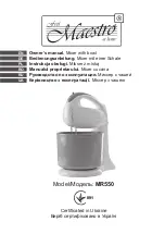
MR550
Brand: Maestro Pages: 52

GM Series
Brand: Faggiolati Pumps Pages: 38

BM10
Brand: Paramount Fitness Pages: 17

MX 1200 PRO
Brand: F.F. Group Pages: 36

14582
Brand: Gizmo Pages: 8
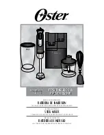
FPSTHB2800
Brand: Oster Pages: 24

Delta Theatre
Brand: SoundCraft Pages: 58

MZ 2619
Brand: Clatronic Pages: 48

DV Promix 3
Brand: Professional Sound Corporation Pages: 4

SIDOMIX
Brand: Wassermann Dental-Maschinen Pages: 16

PRESS Series
Brand: Hotone Pages: 2

419402
Brand: DS Produkte Pages: 44

Clap-522
Brand: MFB Pages: 2

Foodi CI090UK
Brand: Ninja Pages: 2

900636
Brand: Homemaker Pages: 13

VOLUME (X)8
Brand: Dunlop Pages: 5


