

Welcome
Thank you for purchasing the Yamaha MG06X/MG06 Mixing Console.
Please read this manual thoroughly to get the most out of the product and ensure long-term,
trouble-free use. After reading this manual, keep it readily available for future reference.
* For the remainder of this manual, the word “mixer” is used instead of “Mixing Console.”
** In this manual, all panel illustrations show the MG06X panel.
Main Features
• 6-channel mixer features microphone inputs and stereo/mono line inputs for input jacks.
• Yamaha’s premium head amp “D-PRE” for providing high quality sound.
• PAD switch to support a wide variety of inputs to the channels 1/L and 2/R.
• (MG06X) Yamaha’s high-quality SPX effects (6 types), providing optimum processing for
instruments or vocals.
Included Accessories
• AC power adaptor
• Technical Specifications: Includes block diagram, dimensions, general specifications, and
input/output characteristics.
• Owner’s Manual (this leaflet)
Quick Start Guide
STEP 1
Connecting speakers, microphones, and
instruments, etc.
Connection Example
Microphones
Electric acoustic guitar
Electric keyboard
Powered speakers
Headphones
Portable
audio
player
L*
R
R
L
R*
L
R
R
L
L
* Stereo mini plugs require conversion plugs to phone plugs.
STEP 2
Getting Sound to the Speakers
1
Make sure that all switches including the [ ] switch are not pressed (
N
).
2
Connect the supplied AC power adaptor.
First connect the adaptor to the DC IN [12V] jack at the back panel of the unit (
1
),
and then to the outlet (
2
).
1
2
Power adaptor
To electrical outlet
3
Turn the [GAIN], [LEVEL] knobs (white), and [STEREO LEVEL] knob (red)
fully to the left (minimum). Set the equalizer knobs (green) to the center “
6
”
position.
Refer to the illustration (at the top of the next column, before step 4).
ä
Equalizer
LEVEL
GAIN
STEREO LEVEL
4
If you connect a device with high output level, such as a CD player or an
electric keyboard to the channels 1/L and 2/R, turn on (
O
) the [PAD] switch
of the corresponding channel*.
* Channel: Location or path where sound is input.
Channel 1/L
Channel number
Channel 2/R
PAD
NOTE
If you are using condenser microphones, turn on (
O
) the [P48V] switch.
5
Turn on the power to connected devices in the following order:
(microphone),
(instrument),
(audio device)
[
] (switch on unit)
(speakers)
NOTICE
Follow this order to avoid any loud, unexpected noise from the speakers. Reverse the order when
turning the power off.
6
Set the [STEREO LEVEL] knob to the “
3
” position.
7
For channels to which a microphone is connected, set the [GAIN] knob to
roughly the 12 o’clock position.
8
While playing your instrument or speaking into the microphone, turn the
[LEVEL] knob to adjust the volume of the corresponding channel.
9
If necessary, adjust the volume of the speaker or power amp.
If you hear the sound and the volume seems appropriate, setup is complete. If not,
please go to step 10 below.
NOTICE
To avoid any loud noise from the speaker, first turn off the power of the speaker (speaker amp), then
the unit itself, and finally the connected sound source such as an instrument.
10
If the sound is not heard, or if you want to adjust the volume, follow the
instructions in the boxed section below.
If you still do not hear the sound after doing the following steps, please refer to the
checklist in the “Troubleshooting” section at the back of this booklet.
EN
ZG13410
MIXING CONSOLE
Owner’s Manual
<
There is no sound, or you need to increase the volume
1
Turn the [GAIN] knob to the right so that the corre-
sponding [PEAK] LED flashes briefly.
NOTE
If the [PEAK] LED does not light even if the [GAIN] knob has been
turned fully to the right, raise the volume of the sound source
(instrument, etc.).
If no sound is heard or the volume does not increase after step 1:
2
If the [PAD] switch is turned on (
O
), set the [LEVEL]
knob to “0” (minimum), and then turn off (
N
) the
switch.
3
Slowly turn the [LEVEL] knob to the right until the
desired volume is reached.
<
To decrease the volume:
1
Set the [LEVEL] knob to “0” (minimum), then turn on
(
O
) the [PAD] switch.
2
Slowly turn the [LEVEL] knob to the right until the
desired volume is reached.
If the volume does not decrease after the above steps:
3
Lower the volume of the instrument or audio device.
PAD
GAIN
LEVEL
PEAK
Controls and Functions
1
4
2
5
@
)
^
*
#
$
%
B
3
!
8
6
7
9
(
A
&
2
[MIC/LINE] mono input jacks (channels 1/L, 2/R)
Connect a microphone, an instrument, or an audio device (CD
player, etc.) to the unit. These jacks support both XLR and
phone plugs.
XLR
Phone
3
[LINE] stereo input jacks (channels 3/4, 5/6)
Connect line-level devices such as an electric keyboard or
an audio device. These jacks support phone plugs. If you use
only the [L/MONO] jack, same sound is output from both L (left)
and R (right) speakers.
4
[PAD] switches
Turning the switch on (
O
) will attenuate the sound input to the
unit. If you hear distortion or the [PEAK] LED
@
lights, turn the
switch on (
O
).
NOTE
Turn the [LEVEL] knob to "0" (minimum) before toggling
the [PAD] switch on (
O
) and off (
N
). Otherwise, noise
may be produced.
5
[HPF] (High-Pass Filter) switches
Turning the switch on (
O
) will apply a high-pass filter that
attenuates frequencies below 80Hz. When speaking into the
microphone, you may want to turn this switch on (
O
), in order
to reduce unwanted vibration and wind sound received by the
microphone.
@
[PEAK] LED
Lights when the volume of input and/or post-equalizer sound
is too high. If it is lit, turn the [GAIN] knob
8
to the left to lower
the volume.
#
[LEVEL] knobs
For adjusting the volume balance among the channels.
$
[PHONES LEVEL] knob
Adjusts the headphones volume.
%
[STEREO LEVEL] knob
Adjusts the overall volume output from the [STEREO OUT]
output jacks.
1
(Back panel) DC IN [12V] jack
Connect the supplied AC power adaptor to this jack.
6
[STEREO OUT] output jacks
Connect a powered speaker or powered amp. These jacks
support both XLR and phone plugs.
7
[PHONES] output jack
Connect a set of headphones. This jack supports a stereo
phone plug.
^
[P48V] switch/LED
When this switch is on (
O
), the LED lights indicating that the
unit supplies DC+48V phantom power to the XLR plugs of
the [MIC/LINE] mono input jacks
2
. Turn this switch on when
using a phantom-powered condenser microphone.
CAUTION
Be sure to leave this switch off (
N
) if you do not need phantom power.
Follow the important precautions below, in order to prevent noise and
possible damage to external devices as well as the unit when you
operate this switch.
• Be sure to leave this switch off when you connect a device that does
not support phantom power to channels 1/L or 2/R.
• Do not connect/disconnect a cable to/from channels 1/L and 2/R
while this switch is on.
• Turn the [LEVEL] knob of the channels 1/L and 2/R to the minimum
before operating this switch.
&
[ ] (On/Standby) switch
Toggles to turn the unit’s power On (
O
) or Standby (
N
).
CAUTION
• Rapidly switching the unit between on and standby in succession
can cause it to malfunction. After setting the unit to standby, wait for
about 5 seconds before turning it on again.
• Even when the switch is in the standby (
N
) position, electricity is still
flowing to the unit. If you do not plan to use the unit for a while, be
sure to unplug the AC power adaptor from the outlet.
*
[REVERB
N
/
O
DELAY] switch (MG06X)
Toggles to select the effect applied to channels 1/L and 2/R
between Reverb (
N
) and Delay (
O
).
(
Effect select slide switch (MG06X)
Moves up and down to select the effect type. The LED of the
selected effect lights.
A
[FX RTN LEVEL] (effect return level) knob
(MG06X)
Adjusts the volume of the effect sound.
B
Level meter
The L and R meters show the level of the signal output from
the [STEREO OUT] jack. If the [PEAK] lamp lights in red, use
the [LEVEL] knob to lower the volume.
8
[GAIN] knobs
Determines the basic volume for each channel, 1/L and 2/R.
Adjust these so that the corresponding [PEAK] LEDs
@
flash
briefly when singing or playing the loudest.
9
Equalizer (EQ) knobs
Adjust the sound quality by using the [HIGH] (high frequency
band) and [LOW] (low frequency band) knobs. If you do not
need to adjust the sound quality, set the knob to the “
6
” (flat)
position.
)
[FX] switches (MG06X)
Toggle the FX (effect) of channels 1/L and/or 2/R on and off.
!
[
N
MONO/
O
STEREO] switch
(
N
) [MONO]: Sound input to channels 1/L or 2/R can be
heard from both the right and left speakers. If you use the 1/L
or 2/R individually, set the switch to this setting.
(
O
) [STEREO]: Sound input to channel 1/L can be heard from
only the left speaker, and that input to channel 2/R can be
heard from only the right speaker.
Applying Effects (MG06X)
The MG06X features built-in effects (Reverb and Delay) processors that are in the same
league as our famed SPX effect processor series. Those effects let you simulate the
acoustics of different performance environments, such as concert halls and small clubs,
and add warm, natural ambience to your vocals or instrument performance.
1
Use the [REVERB
N
/
O
DELAY] switch to select Reverb (
N
) or Delay (
O
).
Type
Description
REVERB HALL
Reverb simulating a large space such as a concert hall.
ROOM
Reverb simulating the acoustics of a small space (room).
PLATE
Reverb simulating a metal-plate, producing a more hard-edged sound.
DELAY
SHORT
Short echo with a “doubled” sound.
LONG
Long, resonant echo with an extended decay.
VO.ECHO Echo suitable for vocals.
2
Move the effect select slide switch up and down to select the effect type.
The LED of the selected effect lights.
3
Turn on (
O
) the [FX] switch of the channel (1/L or 2/R) to which you want to
apply the effect.
4
Turn the [FX RTN LEVEL] knob to adjust the effect amount.
3
4
2
1
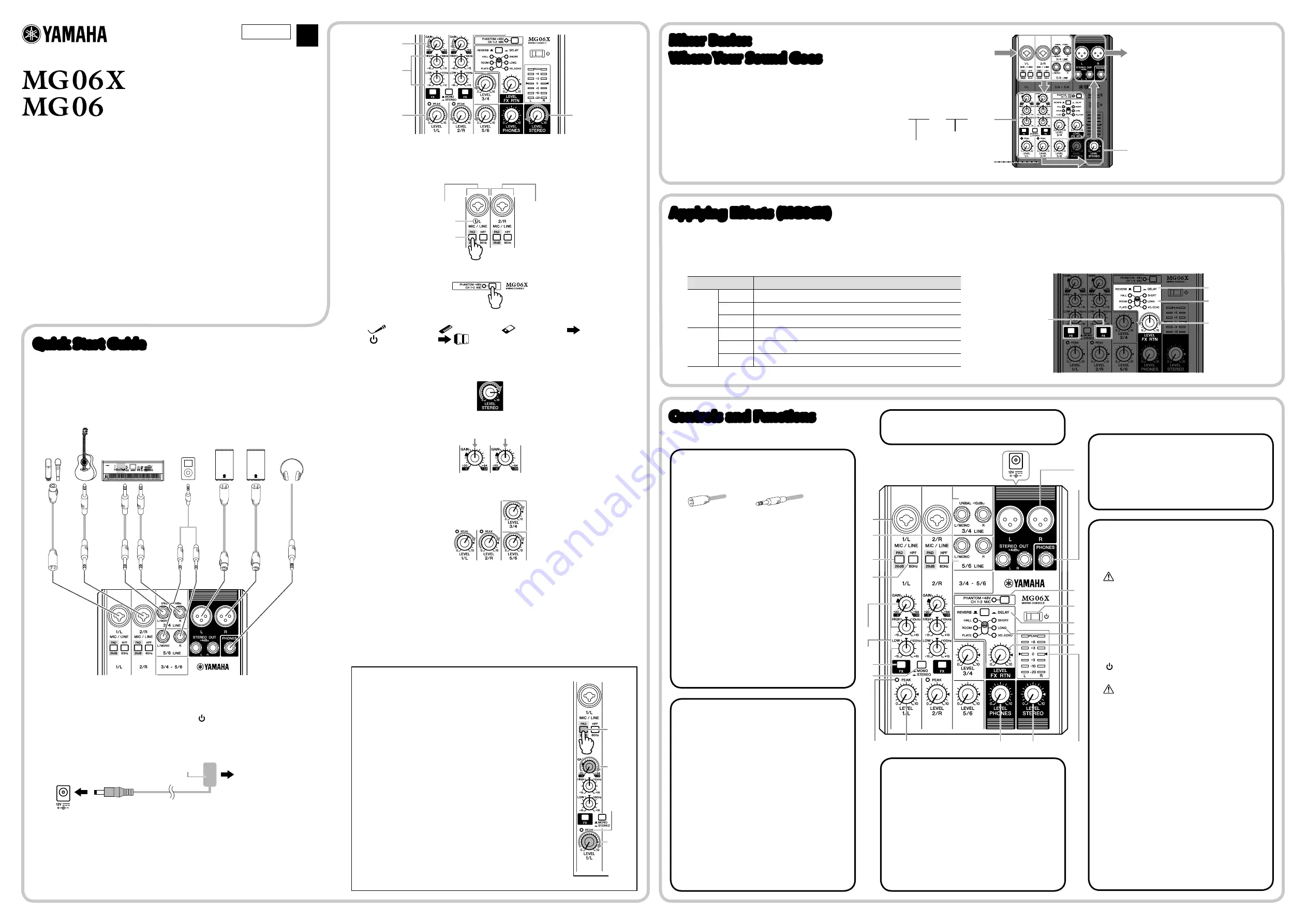
Mixer Basics:
Where Your Sound Goes
The right illustration diagram illustrates the sound
flow from summing (mixing) sound which was
input to the channels to outputting sound from
the speakers or headphones. Let’s find out where
input sound goes once it’s inside the mixer.
1
Input the sound from a microphone or
instrument
5
Output the sound from speakers or
headphones
4
Final adjustment of the volume of the
mixed sound
3
The signal flow of the sound rightward, from
the channels to the final output.
2
Adjust the sound quality and volume of each
channel
Equalizer (HIGH, LOW) knobs
GAIN, LEVEL Knobs


