Woodward ESDR 4, Manual
The Woodward ESDR 4 user manual is essential for understanding and operating this high-quality product efficiently. You can download the manual for free from manualshive.com, providing detailed instructions and maintenance procedures to ensure optimal performance. Get your hands on the manual today to unleash the full potential of your device.
Share
Download


Reviews:
No comments
Related manuals for ESDR 4

7800 Series
Brand: Yamatake-Honeywell Pages: 28

VLT FC 300
Brand: Danfoss Pages: 24

MQTT.box
Brand: W&T Pages: 30

PNOZ e1vp 10
Brand: Pilz Pages: 12

STW1K
Brand: ZIEHL Pages: 6

SAFE M
Brand: RIESE Pages: 9

MTR2000
Brand: Yokis Pages: 12

EMR-4000
Brand: Eaton Pages: 960
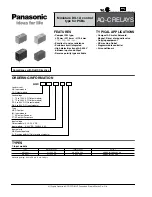
AQ-C Relays
Brand: Panasonic Pages: 5

TR1200IP
Brand: ZIEHL Pages: 23

Z45FK
Brand: Kieback&Peter Pages: 8

PST 4
Brand: Pilz Pages: 8

S3UM/E
Brand: Pilz Pages: 6

DTR-10t
Brand: Entes Pages: 4

DRB-1-1-00
Brand: nodon Pages: 2

SOUNDLIGHT 5202R-EP
Brand: DMX Pages: 15


