


Vorlage Montageanleitungen_Umschlag 13.11.12 10:21 Seite 1
Installation instructions for contractors
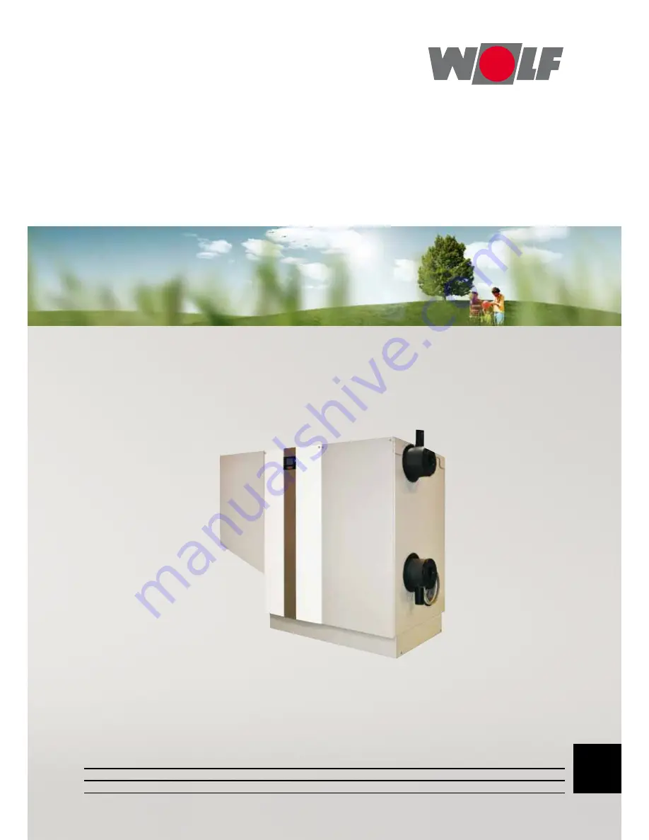
Gas condensing boilers
MGK-2-390
MGK-2-470
MGK-2-550
MGK-2-630
Wolf GmbH
•
Postfach 1380
•
D -84048 Mainburg
•
Tel. +49 (0)8751/74-0
•
Fax +49 (0)8751/74-1600
•
Internet: www.wolf-heiztechnik.de
Document no.: 3063772_201507
Subject to technical modifications
GB
(dt.)


