background image

SERVICE MANUAL INTRODUCTION

This service manual helps with troubleshooting and diagnosing

malfunctions, completion of repairs, and return of the product to

proper operating condition. Read the complete instructions

contained within before initiating any repairs.
This guide is intended for use by Factory Certified Service. Wolf

Appliance, Inc. recommends that only Factory Certified Service

companies do repairs.
Warning and Caution product safety labels appear throughout

this manual. Product safety labels appear at the beginning of

some sections. Follow the instructions in the product safety

labels to avoid personal injury and/or product damage. The

sample safety labels explain the types of notices that appear in

this manual.

  WARNING

States a hazard that may cause serious injury or

death if precautions are not followed.

  CAUTION

Indicates minor injury or product damage may occur

if precautions are not followed.

IMPORTANT NOTE: Highlights especially important information.
TIP: Indicates additional, useful information.
Information and images contained herein are copyright of Wolf

Appliance, Inc. Neither this manual nor any information or

images contained herein may be copied or used in whole or in

part without the express written consent of Wolf Appliance, Inc.

©

 Wolf Appliance, Inc., all rights reserved.

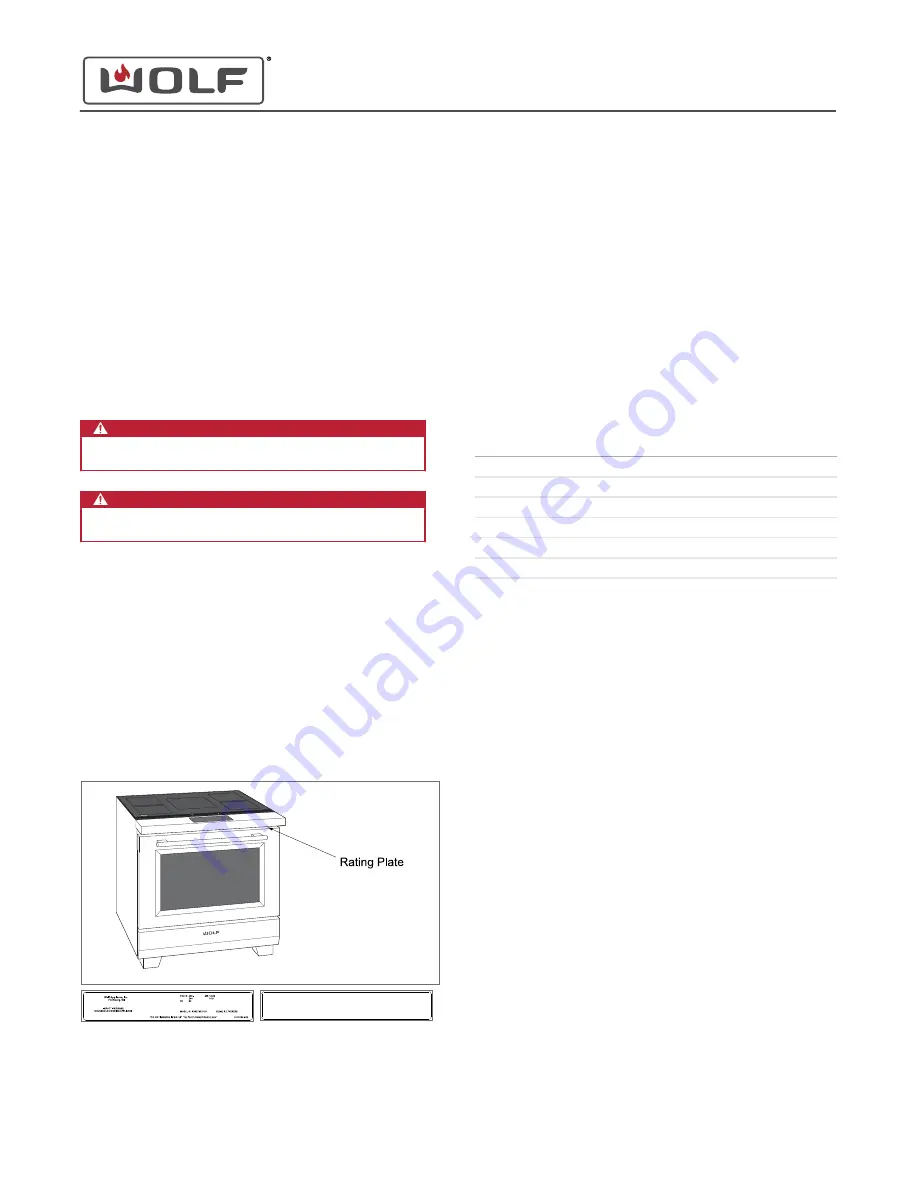
WOLF PRODUCT RATING PLATE INFORMATION

The Induction Range rating plate is located on the bottom of the
bullnose assembly.

Wolf Appliance, Inc. 

Fitchburg, WI

9019151-002

INDUCTION RANGE

HOUSEHOLD COOKING APPLIANCE

Date Code

VOLTS : 220-240~ V          kW: 14.4-16.0 kW

                 380-415 3N~ V             7.0-7.6 kW

Hz          : 50/60                             IPX0

MODEL #: ICBIR36550/S/TH        SERIAL #: 17XXXXXX

Important information for each product is listed on the product
rating plate. Rating plates identify:

Model

Serial number

Electrical information

MODEL DESCRIPTIONS AND SALES ACCESSORIES

For more details on individual model descriptions and a listing
of all compatible sales accessories, see the 

Wolf Product and

Sales Accessory Reference Guide

.

INDUCTION RANGE MODEL KEY

Model Character

Description

IR

Induction Range

30

 or 36

Unit width

4 or 5

Number of induction burners

50

Model differentiator

/S

Stainless steel

/T

Tubular style handle

PRODUCT USE AND CARE AND INSTALLATION GUIDES

Product use and care guides, installation guides, and other
product specifications are available in the 

Product

Specifications and Manuals Library

.

UNIT WARRANTY

Product warranty is determined by the installation location and
the date of installation.

View product warranties at 

http://service.subzero.com/

ClaimsAndOrderProcessing/Pages/WarrantyInfo

.

Warranties start on the day of product installation.

Search for warranty and service information by serial
number, customer last name, and address using Unit
History at 

http://service.subzero.com/Tools/UnitHistory

.

30" and 36" Induction Range

General Information

GENERAL INFORMATION 

service.subzero.com

829191 REVA     

1


Summary of Contents for Drawer Microwave Oven

Page 1: ...ATION The Induction Range rating plate is located on the bottom of the bullnose assembly Wolf Appliance Inc Fitchburg WI 9019151 002 INDUCTION RANGE HOUSEHOLD COOKING APPLIANCE Date Code VOLTS 220 240 V kW 14 4 16 0 kW 380 415 3N V 7 0 7 6 kW Hz 50 60 IPX0 MODEL ICBIR36550 S TH SERIAL 17XXXXXX Important information for each product is listed on the product rating plate Rating plates identify Model...

Page 2: ...on the display The Home screen appears 2 Touch Settings The Settings screen appears 3 Scroll to Language on the UIM Touch Language The Language Selection screen appears The available languages are English Spanish French German Italian Dutch Chinese 4 Scroll left or right to highlight the desired language Touch the highlighted selection The Set Language screen appears 5 Touch Set The Home screen ap...

Page 3: ...oll left or right to highlight the 12 Hour or 24 Hour option Touch the highlighted selection The Select Current Time screen appears 5 Scroll up or down to highlight the hour and minute If the 12 Hour option is selected scroll to select AM or PM 6 Touch Set The Home screen appears 30 and 36 Induction Range Settings Set the Time continued service subzero com 829191 REVA 3 ...

Page 4: ...the unit Choices include Dutch English French German Italian Chinese and Spanish Units Set the measurement units to either imperial or metric Showroom For use by showrooms only If Showroom Mode is on the oven is not useful for normal operation Info Information about the icons on the UIM settings and cooking modes About System information including the oven serial number Temp Offset Increase or dec...

Page 5: ...ed scroll to select AM or PM 6 Touch Set The Home screen appears SET SABBATH MODE 1 Touch the time on the display The Home screen appears 2 Touch Settings The Settings screen appears 3 Scroll to select Sabbath on the UIM Touch Sabbath The Sabbath screen appears 4 Scroll left or right to highlight the On or Off option Touch the highlighted selection The Sabbath Set screen appears 30 and 36 Inductio...

Page 6: ...h 9 Touch Timed Cook The Select Cook Time Duration screen appears 10 Touch Set The Stop Time screen appears Scroll to select the hour and minutes and set the stop time Changing the stop time changes the time the oven starts heating If the stop time is not adjusted the oven starts immediately If the stop time is the next day Tomorrow appears 11 Touch Set The cooking mode screen appears 30 and 36 In...

Page 7: ...y Style screen appears 4 Scroll left or right to highlight the Analog Logo Blank or Digital option Touch the highlighted selection The Clock Set screen appears 5 Touch Set The Home screen appears ENABLE THE CONNECTED FEATURE 1 Touch the time on the display The Home screen appears 30 and 36 Induction Range Settings Set the Clock Style continued service subzero com 829191 REVA 7 ...

Page 8: ...ight to highlight On or Off Touch the highlighted selection The Connect Set screen appears 5 Touch Set The Home screen appears SET STANDBY 1 Touch the time on the display The Home screen appears 2 Touch Settings The Settings screen appears 30 and 36 Induction Range Settings ENABLE THE CONNECTED FEATURE continued service subzero com 829191 REVA 8 ...

Page 9: ...Set The Home screen appears SET THE LANGUAGE 1 Touch the time on the display The Home screen appears 2 Touch Settings The Settings screen appears 3 Scroll to Language on the UIM Touch Language The Language Selection screen appears The available languages are English Spanish French German Italian Dutch Chinese 30 and 36 Induction Range Settings SET STANDBY continued service subzero com 829191 REVA ...

Page 10: ... Touch Settings The Settings screen appears 3 Scroll to Units on the UIM Touch Units The Units Selection screen appears 4 Scroll left or right to highlight the desired units Touch the highlighted selection The Set Units screen appears 5 Touch Set The Home screen appears SET SHOWROOM MODE 1 Touch the time on the display The Home screen appears 30 and 36 Induction Range Settings SET THE LANGUAGE con...

Page 11: ... selection The Set Showroom screen appears 5 Touch Set The Home screen appears When the unit is in Showroom Mode Showroom appears on the Home screen OPTION INFO 1 Touch the time on the display The Home screen appears 2 Touch Settings The Settings screen appears 3 Scroll to Info on the UIM 30 and 36 Induction Range Settings SET SHOWROOM MODE continued service subzero com 829191 REVA 11 ...

Page 12: ...re Quick Start Gourmet Connect Lock Time Settings Timer 1 Light Timer 2 The options under the Quick Start menu are Stone Bake Convection Broil Convection Roast Roast Clean Warm Proof Dehydrate The options under the Settings menu are Sabbath Clock Connect Standby Language Units Showroom About Temp Offset Brightness Sound Calibration The options under the Cooktop menu are Universal Off Lock Zone Ind...

Page 13: ...internet address Unit model number Unit serial number SYS system version number GUI graphic users interface version number CFG configuration version number HV1 high voltage 1 version number LV1 low voltage 1 version number ADJUST TEMPERATURE OFFSET 1 Touch the time on the display The Home screen appears 2 Touch Settings The Settings screen appears 30 and 36 Induction Range Settings About Unit Info...

Page 14: ...the display The Home screen appears 2 Touch Settings The Settings screen appears 3 Scroll to Calibration on the UIM Touch Calibration The Calibration screen appears 4 Touch the white dot on the display 5 After touching the white dot in the four corners of the display the white dot appears in the center Touch the center white dot The calibration is complete and the Home screen appears 30 and 36 Ind...

Page 15: ...t or Keypad to set the sound for that option Touch the selected option The Volume screen appears 5 Scroll to select Mute 1 2 3 4 or 5 Touch the selected volume The Tone screen appears 6 Scroll to select Low Medium or High Touch the selected tone The Set screen appears 7 Touch Set The Home screen appears 30 and 36 Induction Range Settings Adjust Volume and Tone continued service subzero com 829191 ...

Page 16: ...rightness on the UIM Touch Brightness The Brightness screen appears 4 Scroll to adjust the brightness between 0 and 100 in 5 increments Touch the selected percentage The Brightness Set screen appears 5 Touch Set The Home screen appears 30 and 36 Induction Range Settings Adjust Brightness continued service subzero com 829191 REVA 16 ...

Page 17: ...nv 325 F 160 C 200 F 95 C 550 F 285 C Proof 85 F 30 C 85 F 30 C 110 F 45 C Dehydrate 135 F 55 C 110 F 45 C 170 F 75 C Stone 450 F 230 C 200 F 95 C 550 F 285 C BAKE MODE 1 Touch the time on the display The Home screen appears 2 Touch Quick Start the Select Mode screen appears Scroll until Bake is centered 3 Touch Bake The set temperature screen appears Adjust the temperature by scrolling left or ri...

Page 18: ...h Broil The Adjust Oven Temperature screen appears Set the Broil mode to High Medium or Low Adjust the temperature by scrolling left or right Touching the centered setting turns the oven on at the indicated setting 4 There is no preheat for Broil Mode ROAST MODE 1 Touch the time on the display The Home screen appears 30 and 36 Induction Range Cooking Modes BAKE MODE continued service subzero com 8...

Page 19: ... minus small increments Touching the centered temperature turns the oven on at the indicated temperature 4 The oven enters preheat 5 When the preheat is complete the oven chimes once CLEAN MODE 1 Touch the time on the display The Home screen appears 2 Touch Quick Start and the Select Mode screen appears Scroll until Clean is centered 30 and 36 Induction Range Cooking Modes ROAST MODE continued ser...

Page 20: ...own 6 When the Clean cycle is complete the oven chimes four times The oven door unlocks when the temperature is below 550 F 288 C WARM MODE 1 Touch the time on the display The Home screen appears 2 Touch Quick Start and the Select Mode screen appears Scroll until Warm is centered 30 and 36 Induction Range Cooking Modes CLEAN MODE continued service subzero com 829191 REVA 20 ...

Page 21: ...he time on the display The Home screen appears 2 Touch Quick Start and the Select Mode screen appears Scroll until Roast is centered 3 Touch the Roast The Adjust Oven Temperature screen appears Adjust the temperature by scrolling left or right large increments or touching plus or minus small increments Touching the centered temperature turns the oven on at the indicated temperature 4 The oven ente...

Page 22: ...nv The Adjust Oven Temperature screen appears Adjust the temperature by scrolling left or right large increments or touching plus or minus small increments Touching the centered temperature turns the oven on at the indicated temperature 4 The oven enters preheat 5 When the preheat is complete the oven chimes once 30 and 36 Induction Range Cooking Modes CONVECTION ROAST MODE continued service subze...

Page 23: ...rolling left or right large increments or touching plus or minus small increments Touching the centered temperature turns the oven on at the indicated temperature 4 The oven enters cooking DEHYDRATE MODE 1 Touch the time on the display The Home screen appears 2 Touch Quick Start and the Select Mode screen appears Scroll until Dehy is centered 30 and 36 Induction Range Cooking Modes Proof Mode cont...

Page 24: ...e on the display The Home screen appears 2 Touch Quick Start and the Select Mode screen appears Scroll until Stone is centered 3 Touch Stone The Adjust Oven Temperature screen appears Adjust the temperature by scrolling left or right large increments or touching plus or minus small increments Touching the centered temperature turns the oven on at the indicated temperature 4 The oven enters preheat...

Page 25: ...t and the Gourmet screen appears 3 Scroll to select an option on the UIM Touch the selection The second Gourmet screen appears 4 Scroll to select an option on the UIM Touch the selection If there are no further options the Done screen appears 5 Touching Done shows information for getting the food ready for cooking 6 Place the food in the oven according to the instructions 7 Touch Start The number ...

Page 26: ...check that the oven cavity is clear and then close the door message appears 3 Open and close the oven door 4 The customer can now connect to the appliance using the Sub Zero Group Owner s App 30 and 36 Induction Range Cooking Modes CONNECT MODE continued service subzero com 829191 REVA 26 ...

Page 27: ...ooking modes Timed countdown Useable when oven is not running Timer 2 Home screen and cooking modes Timed countdown Useable when oven is not running Light Home screen and cooking modes Turn the oven light on or off Set on or off for the length of Sabbath LOCK 1 On the time display of the UIM Lock in bold means that the UIM is locked 2 Touch and hold Lock for 3 seconds The Home screen appears Lock ...

Page 28: ...ting the oven insert the probe when placing the food into the oven 8 The oven enters preheat 9 When cooking is in progress the probe registers the internal temperature of the food When the probe temperature reaches 5 F 3 C below the set temperature the oven chimes once When set temperature is reached the unit chimes and flashes The probe temperature range is 120 F 50 C to 210 F 100 C Probe Temp ap...

Page 29: ...ff at the time set The probe is not available in Timed Cook TIMER 1 AND TIMER 2 1 From the Home screen or cooking mode touch Timer 1 or Timer 2 2 The Timer 1 or Timer 2 screen appears Scroll to select the hour and minutes and set the amount of cooking time Hours From 0 hours to 99 hours Minutes From 0 minutes to 59 minutes 3 Touch Set The screen returns to the Home screen or cooking mode Timer 1 i...

Page 30: ...n light turns on Light on the screen turns bold Turning the light on or off in Sabbath Mode lasts for as long as the unit is in Sabbath 30 and 36 Induction Range Auxilary Controls Light continued service subzero com 829191 REVA 30 ...

Page 31: ...en cooking time in minutes Control Relay status Bake Broil Lamp Conv left element and fan Conv right element and fan Door lock Conv left fan Conv right fan Cooling fan with RPM Sensors Two screens PCM temp PCM voltage PCM frequency RTD temp Probe temp Oven door Door lock GENERAL DIAGNOSTICS 1 Touch the time on the display The Home screen appears 2 Touch Settings The Settings screen appears 3 Scrol...

Page 32: ...t The Self Test Running screen appears 2 The Self Test Running screen shows the progress of the self test 3 Once self test is complete the results appear 4 Touch OK The Diagnostics menu or Faults screen appears Change the Model 1 On the Diagnostics menu touch Change Model The Choose Model screen appears 30 and 36 Induction Range Diagnostics service subzero com 829191 REVA 32 ...

Page 33: ...tion Screen The Adjust Screen Position screen appears 2 Touch the arrows to adjust the screen position 3 Touch Set The Diagnostics menu appears Test Screen 1 On the Diagnostics menu touch Test Screen The Test screen appears 2 The Test screen is a series of screens red green blue white black and checkered that shows any bad pixels in the UIM display 30 and 36 Induction Range Diagnostics CHANGE THE ...

Page 34: ...appears 3 Scroll to About on the UIM Touch About The About screen appears 4 The About screen provides information on the unit 5 Touch and hold OK for 5 seconds The Diagnostics menu appears 6 Touch the Faults tab 30 and 36 Induction Range Diagnostics Faults continued service subzero com 829191 REVA 34 ...

Page 35: ... for three seconds STATISTICS 1 Touch the time on the display The Home screen appears 2 Touch Settings The Settings screen appears 3 Scroll to About on the UIM Touch About The About screen appears 4 The About screen provides information on the unit 5 Touch and hold OK for 5 seconds The Diagnostics menu appears 30 and 36 Induction Range Diagnostics Faults Tab continued service subzero com 829191 RE...

Page 36: ...Number of minutes the unit was in standby Number of minutes in a cooking mode ACTIVATE COMPONENTS 1 Touch the time on the display The Home screen appears 2 Touch Settings The Settings screen appears 3 Scroll to About on the UIM Touch About The About screen appears 4 The About screen provides information on the unit 30 and 36 Induction Range Diagnostics service subzero com 829191 REVA 36 ...

Page 37: ...nds Relay Status When a relay closes Active appears When the relay opens Inactive appears When the cooling fan relay is turned on the cooling fan RPM appears SENSORS 1 Touch the time on the display The Home screen appears 2 Touch Settings The Settings screen appears 3 Scroll to About on the UIM Touch About The About screen appears 30 and 36 Induction Range Diagnostics service subzero com 829191 RE...

Page 38: ...uch the Sensors tab The Sensors screen appears Sensors Tab 1 On the Sensors tab information on the sensors appears 2 There are multiple screens of oven feedback To scroll through the sensors touch the arrow keys on the right hand side of the screen 30 and 36 Induction Range Diagnostics service subzero com 829191 REVA 38 ...

Page 39: ... Place the cooktop in Idle mode 2 Touch or to select the zone to energize The white area on the icon is the zone being selected 3 Touch a power setting Melt Simmer power level 1 Power level from 2 to 9 High power level 10 Boost 4 To bridge vertically adjacent zones touch 5 Touch or to turn the zone off Touch to turn all of the cooktop zones off LOCK MODE To place the cooktop in Lock Mode With the ...

Page 40: ...r frequency Touch the left front high to increase the annunciator frequency The cooktop beeps at each new frequency setting The annunciator frequency range is one to three Touch the left rear low to move backward to annunciator volume setting Touch the left rear high to move forward to Auto Lock Touch to return to the lock setting Not touching the cooktop for 30 seconds returns the cooktop to the ...

Page 41: ...ntering Diagnostics Mode one dot appears on the left rear power level selector TIP The fully illuminated dots in the image are shown larger for clarity All LED indicators for all control zones are on The display lock hot and boost LEDs are on Touch the left front low or high cycles the LEDs through on dim and off Touch the left rear high to move forward to Generator Reconfiguration setting Touch t...

Page 42: ...selector The display shows the current heat sink state 0 temperature is 80 C Everything works as expected 1 temperature is 80 C Boost is disabled for the affected zones 2 temperature is 89 C Affected zone is limited to 60 power Zones will be limited to 40 power when the temperature is 94 C 3 temperature is 99 C All affected zones are turned off The left front low and high are dimmed The left front...

Page 43: ... display shows the current error code The left front control zone shows 0 8 dimmed dots based on how many error codes have been logged A fully illuminated dot on the left front control indicates which error code is shown If only a single error has been logged only a single fully illuminated LED is shown If more than eight error codes are logged the error log acts as a ring buffer with the most rec...

Page 44: ...sion of the control If the software version exceeds two digits then the display alternates between every two digits of the version number Touch the left rear low to move backward to Error Code Readout Touch to return to the lock setting Not touching the cooktop for 30 seconds returns the cooktop to the lock setting 30 and 36 Induction Range Cooktop Controls SOFTWARE VERSION INDICATOR continued ser...

Page 45: ...d CAUTION Metal edges may be sharp Use caution when servicing unit to avoid personal injury Unit Removal Uninstall the unit when directed by a procedure or when access to a necessary component requires uninstalling the unit Any repair to the Induction Range Cooktop requires the unit to be removed from the installation Uninstall the Unit 1 Turn off the power to the unit 2 Remove the unit from the i...

Page 46: ...ole slots on the back of the bullnose 4 Set the cooktop into the unit frame 5 Use a T 20 Torx bit to install the screws into the unit GLASS ASSEMBLY REMOVAL WARNING Disconnect the product from the power source before starting this procedure To remove the glass assembly first uninstall the unit Then remove 1 Cooktop Remove the Glass Assembly 1 Use a T 20 Torx bit to remove the screws from the glass...

Page 47: ...r source before starting this procedure To remove the coil assembly first uninstall the unit Then remove 1 Cooktop 2 Glass assembly Remove the Coil Assembly 1 Use a small flat blade screwdriver to lift the coil assembly from the wire side of the coil assembly 2 Use a T 25 Torx bit or large flat blade screwdriver to loosen the terminal screws holding the coil assembly wire connectors Remove the wir...

Page 48: ...rx bit to start the screws that mount the generator plate to the generator 4 Use a T 20 Torx bit to start the screws that mount the generator plate to the generator support 5 Use a T 15 Torx bit to install the ground screw into the coil wire connector opening 6 Use a T 15 and T 20 Torx bit to tighten all screws SWITCH MODE POWER SUPPLY REMOVAL WARNING Disconnect the product from the power source b...

Page 49: ...y wire harness to the generator GENERATOR ASSEMBLY REMOVAL WARNING Disconnect the product from the power source before starting this procedure To remove the generator assembly first uninstall the unit Then remove 1 Cooktop 2 Glass assembly 3 Coil assembly 4 Generator plate Remove the Three Burner or Four Burner Generator Assembly 1 Remove the wire harness connector from the generator support 2 If ...

Page 50: ...generator assembly into the generator mounting support 2 Connect the wire connectors and wire harnesses to the two burner generator assembly BULLNOSE REMOVAL WARNING Disconnect the product from the power source before starting this procedure To remove the bullnose first uninstall the unit Then remove 1 Cooktop 2 Oven door 3 Skirt 4 Cover collar Remove the Bullnose 1 Disconnect the wire harness fro...

Page 51: ...board is found beneath the exhaust vents behind the shirt 1 Use a T 20 Torx bit to remove the relay board tray mounting screws 2 Press the front clip down Pull the relay board tray forward and remove the relay board bracket from the relay board tray 3 Remove all wire connectors wire harnesses and ribbon cables from the relay board 4 Remove the relay board from the unit RELAY BOARD INSTALLATION Aft...

Page 52: ...doffs DISPLAY CONTROL ASSEMBLY REMOVAL WARNING Disconnect the product from the power source before starting this procedure To remove the display control assembly first uninstall the unit Then remove 1 Cooktop 2 Oven door 3 Skirt 4 Cover collar 5 Bullnose Remove the Display Control Assembly 1 Use a T 20 Torx bit to remove the screws from the lower bullnose cover 2 Remove the lower bullnose cover fr...

Page 53: ...l assembly onto the display mounting support 3 Install the display mounting support with the display control assembly into the bullnose 4 Use a T 20 Torx bit to install the screws into the display mounting support 5 Install the lower bullnose cover into the bullnose 6 Use a T 20 Torx bit to install the screws into the lower bullnose cover 30 and 36 Induction Range Electronic Component Removal and ...

Page 54: ...a T 20 Torx bit to loosen the recessed screws in the top of the door 2 Use a T 20 Torx bit to remove the screws at the bottom of the door 3 Slide the door liner toward the bottom of the door skin several inches 4 Lift the door liner away from the door skin OVEN DOOR LINER INSTALLATION After installing the oven door liner install 1 Oven door Install the Oven Door Liner 1 Place the door liner onto t...

Page 55: ...or liner 2 Oven door Install the Door Handle CAUTION Torque the door handle mounting screws to 16 in lb Over tightening the door handle mounting screws cracks the door glass CAUTION The pro handle standoffs have a small pin that fits into the stainless steel door skin If the pin is not seated into the hole the door glass may crack 1 Place the door handle onto the front of the door skin 2 Use a T 2...

Page 56: ... install 1 Oven door Install the Skirt 1 Place the skirt onto the hooks of the unit 2 Use a T 20 Torx bit to install the skirt mounting screws COVER COLLAR REMOVAL To remove the cover collar first remove 1 Oven door 2 Skirt Remove the Cover Collar 1 Use a T 20 Torx bit to remove the lower screws 2 Use a T 15 Torx bit to remove the right door bumper 3 Use a 3 16 Allen wrench press in the door switc...

Page 57: ...remove the front duct screws 2 Remove the front duct from the unit 3 Use a T 20 Torx bit to remove the bottom access cover screws 4 Remove the bottom access cover from the unit EXHAUST DUCT INSTALLATION After installing the exhaust duct install 1 Cover collar 2 Skirt 3 Oven door Install the Exhaust Duct 1 Place the bottom access cover into the unit 2 Use a T 20 Torx bit to install the bottom acces...

Page 58: ... 2 Skirt 3 Oven door Install the Gasket 1 Use a T 15 Torx bit to loosely install the gasket clips 2 Insert the gasket beneath the gasket clips 3 Use a T 15 Torx bit to tighten the screws of the gasket clips DOOR SWITCH ASSEMBLY REMOVAL WARNING Disconnect the product from the power source before starting this procedure To remove the door switch assembly first remove 1 Oven door 2 Skirt 3 Cover coll...

Page 59: ... Oven door Remove the Intake Baffle 1 Use a T 20 Torx bit to remove the intake baffle mounting screws 2 Pull the intake baffle forward 3 Remove the intake baffle from the unit Dual Fuel unit shown INTAKE BAFFLE INSTALLATION After installing the intake baffle install 1 Oven door Install the Intake Baffle 1 Place the intake baffle against the back of the oven cavity 2 Use a T 20 Torx bit to install ...

Page 60: ... fan and move the top of the fan toward the front of the unit 3 Pull the convection fan forward 4 Disconnect the convection fan wire harness from the unit harness 5 Remove the convection fan from the unit Dual Fuel unit shown CONVECTION FAN INSTALLATION After installing the convection fan first push the bake tray assembly back into the oven Then install 1 Oven baffle 2 Intake baffle 3 Gasket 4 Cov...

Page 61: ...ion element mounting screws BROIL ELEMENT REMOVAL WARNING Disconnect the product from the power source before starting this procedure To remove the broil element first remove 1 Oven door Remove the Broil Element 1 Use a T 20 Torx bit to remove the the broil element 2 Use needle nose pliers to disconnect the wire connectors from the broil element terminals 3 Remove the broil element from the unit B...

Page 62: ...e the Smoke Catalyst 1 Use a T 20 Torx bit to remove the mounting screws from the smoke catalyst 2 Pull the smoke catalyst down into the oven cavity 3 Remove the smoke catalyst from the unit SMOKE CATALYST INSTALLATION After installing the smoke catalyst install 1 Broil element panel 2 Broil element 3 Oven door Install the Smoke Catalyst 1 Place the smoke catalyst into the oven cavity 2 Use a T 20...

Page 63: ...rom the unit BAKE TRAY ASSEMBLY INSTALLATION After installing the bake tray assembly install 1 Gasket 2 Cover collar 3 Skirt 4 Oven door Install the Bake Tray Assembly 1 Connect the wire connectors to the bake tray assembly 2 Place the bake tray assembly into the unit 3 Place the cavity bottom panel onto the bake tray assembly 4 Push the bake tray assembly back to the rear wall 5 Use the T 20 Torx...

Page 64: ...Fan If doing the Induction Range alternate method do only step 4 then step 3 1 Use a T 20 Torx bit to remove the two cooling fan bracket mounting screws 2 Remove the cooling fan with the cooling fan bracket from the unit 3 Disconnect the wire harnesses from the cooling fan 4 Use a T 20 Torx bit to remove the cooling fan bracket mounting screws from the cooling fan COOLING FAN INSTALLATION After in...

Page 65: ...to remove the thermal limiter bracket mounting screws 2 Remove the wire connectors from the TCO 3 Use a T 20 Torx bit to remove the TCO mounting screws from the thermal limiter bracket 4 Remove the TCO from the unit THERMAL CUTOUT TCO INSTALLATION After installing the TCO install 1 Cooling fan 2 Back plate Then install the unit For the Induction Range alternate method after installing the TCO inst...

Page 66: ...he user to enter a cooking clean mode The criteria for these errors is that they are likely to limit the proper functionality of the system and would normally cause some customer dissatisfaction These errors can be canceled and are not shown again until the user again attempts to start a mode Any active function in the cavity for which the error has scope are canceled upon generation of the priori...

Page 67: ...n 2 Right oven 1 Replace the relay board 1122 eRConvElementDriveOpen 2 Left oven 1 Replace the relay board 1421 eLConvElementDriveOpen 2 Right oven 1 Replace the relay board 1422 eLConvElementDriveOpen 2 Left oven 1 Replace the relay board 0221 eBakeElementDLBShorted 2 Right oven Right or left oven bake right convection element DLB relay shorted 1 Replace the relay board 0222 eBakeElementDLBShorte...

Page 68: ...open when it should be conducting 1 Check the left convection fan circuit 2 Replace the relay board 1A32 eLConvFanDriveOpen 3 Left oven 1 Check the left convection fan circuit 2 Replace the relay board 1B21 eCoolingFanDriveOpen 2 Right oven The drive circuit for the cooling fan is open when it should be conducting 1 Check the cooling fan circuit 2 Replace the relay board 1B22 eCoolingFanDriveOpen ...

Page 69: ...elay board detects an error with the RS485 network 1 Check the RS485 circuitry 2 Replace the relay board 2C22 ePCMRs485NetworkFault 2 Left oven 1 Check the RS485 circuitry 2 Replace the relay board 3031 eTemperatureProbeShorted 3 Right oven The temperature probe is broken The socket is broken or wired wrong Probe circuit reporting below 1k Ω 1 Check the probe circuitry 2 Replace the relay board 30...

Page 70: ...tion 3 Replace the relay board 3821 eBakeBankWiringFault 2 Right oven The incoming voltage on an element bank is irregular or not detected 1 Check the bake element wiring 2 Check voltage to the bake element 3 Replace the relay board 3822 eBakeBankWiringFault 2 Left oven 1 Check the bake element wiring 2 Check voltage to the bake element 3 Replace the relay board 3921 eBroilBankWiringFault 2 Right ...

Page 71: ...aryInvalidMDLSwitchPosi tion 2 Right oven The MDL lock switch and unlock switch are closed at the same time 1 Check the MDL 2 Check the oven door 3722 eSecondaryInvalidMDLSwitchP osition 2 Left oven 1 Check the MDL 2 Check the oven door 5021 ePrimaryHighTemperatureDurin gClean 2 Right oven The RTD senses a temperature above 950 F 510 C while in clean mode 1 Check the oven temperature 2 Check the R...

Page 72: ...t 2 UIM The UIM display has a fault 1 Reset the power supply 2 Reseat the UIM wire connections 3 Replace the UIM 9010 ePODTouchScreenFault 2 ECH The touch screen is not responding to inputs 1 Reset the power supply 2 Reseat the ECH wire connections 3 Replace the ECH 2F21 Generic Hardware error High Voltage 2 Right relay board Hardware fault on the high voltage control of the relay board 1 Replace ...

Page 73: ... open 1 Check the convection fan connections 2 Replace the relay board 4532 Right convection fan shorted 2 Left oven No load detected when the convection fan is turned on Or the drive circuit for the convection fan is conducting when it should be open 1 Check the convection fan connections 2 Replace the relay board 4631 Left convection fan shorted or missing 2 Right oven No load detected when the ...

Page 74: ...has reset the relay board 1 Replace the relay board A026 Relay board over temperature ambient 2 Left relay board The relay board ambient temperature sensor is over 217 F 103 C 1 Replace the relay board A027 Relay board over temperature ambient 2 Right relay board The relay board ambient temperature sensor is over 217 F 103 C 1 Replace the relay board A0C0 Relay board RS485 wasted frames 2 Left rel...

Page 75: ...ions error Not currently used E 07 TC temperature too high Primary Primary is too hot 1 Check airflow for blockage 2 Replace primary control board E 08 Invalid generator configuration Generator 1 Cycle the unit electrical supply 2 Replace the induction generator E 09 Coil assembly 1 temperature too high Generator 1 Replace the coil assembly 2 Replace the induction generator E 10 Coil assembly 2 te...

Page 76: ...ler 1 Cycle the unit electrical supply 2 Replace the primary and secondary control boards 3 Replace the induction generator E 30 Generator relay error Generator 1 Cycle the unit electrical supply 2 Replace the induction generator E 31 Not valid as of V0 15 See E 39 E 40 E 41 E 42 E 43 E 32 Invalid potentiometer Generator 1 Cycle the unit electrical supply 2 Replace the induction generator E 33 Coi...

Page 77: ...he primary control board E 47 Power supply error on primary Primary Voltage regulator on the primary broken 1 Replace the primary control board E 48 Power supply error on left secondary Left secondary Voltage regulator on the left secondary is broken 1 Replace the left secondary control board E 49 Power supply error on right secondary Right secondary Voltage regulator on the right secondary is bro...

Page 78: ...too high Right secondary Right secondary is too hot 1 Replace the right secondary control board E 58 Not currently in use E 59 Not currently in use E 60 Low voltage detected Primary 1 Check voltage supply 2 Replace primary control board E 61 Hardware error primary Primary NTC failure 1 Check the NTC circuit 2 Replace the primary control board E 62 Hardware error left secondary Left secondary NTC f...

Page 79: ...231 0 6 Hours 4 4 16 50 231 0 429 0 346 5 346 5 6 Hours 5 5 22 00 308 0 572 0 462 0 462 0 6 Hours 6 6 26 50 371 0 689 0 556 5 556 5 6 Hours 7 7 35 50 497 0 923 0 745 5 745 5 6 Hours 8 8 50 00 700 0 1300 0 1050 0 1050 0 2 Hours 9 9 75 00 1050 0 1950 0 1575 0 1575 0 2 Hours 10 HI 100 00 1400 0 2600 0 2100 0 2100 0 2 Hours Boost Boost N A 2200 0 3700 0 3700 0 3700 0 15 Minutes 30 Cooktop Boost Perfor...

Page 80: ... 0 1575 0 1575 0 2 Hours 10 HI 100 00 2100 0 2100 0 2600 0 2100 0 2100 0 2 Hours Boost Boost N A 3700 0 3700 0 3700 0 3700 0 3700 0 15 Minutes 36 Cooktop Boost Performance The two left coils form a group The center coil is its own group The two right coils form a group Each group is visually limited to 4200 W If either of the left coils are on Boost the other left coil is limited to Power Level 5 ...

Page 81: ...n Left 829678 208 26 Fan Convection Right 829679 208 26 Cooling Fan 829682 230 65 Meat Probe 823261 Element Broil 823360 240 3600 15 6 Element Bake 823359 240 3500 15 96 cold Element Bake 36 821890 240 3500 16 2 cold Coil 2600 Watts 826061 2600 49 mOhms 25º Coil 2100 Watts Coil Variant 2100 Watts 826062 826071 2100 43 mOhms 25º Note Actual readings may vary by 10 30 and 36 Induction Range Technica...

Page 82: ...INDUCTION RANGE WIRING DIAGRAMS 30 and 36 Induction Range Wiring Diagrams WIRING DIAGRAMS service subzero com 829191 REVA 82 ...

Page 83: ...30 and 36 Induction Range Wiring Diagrams Induction Range Wiring Diagrams service subzero com 829191 REVA 83 ...

Page 84: ...30 and 36 Induction Range Wiring Diagrams service subzero com 829191 REVA 84 ...

Reviews: