background image

WinSystems, Inc.   |   715 Stadium Drive, Arlington, Texas 76011   |   817-274-7553   |   info@winsystems.com   |   www.winsystems.com
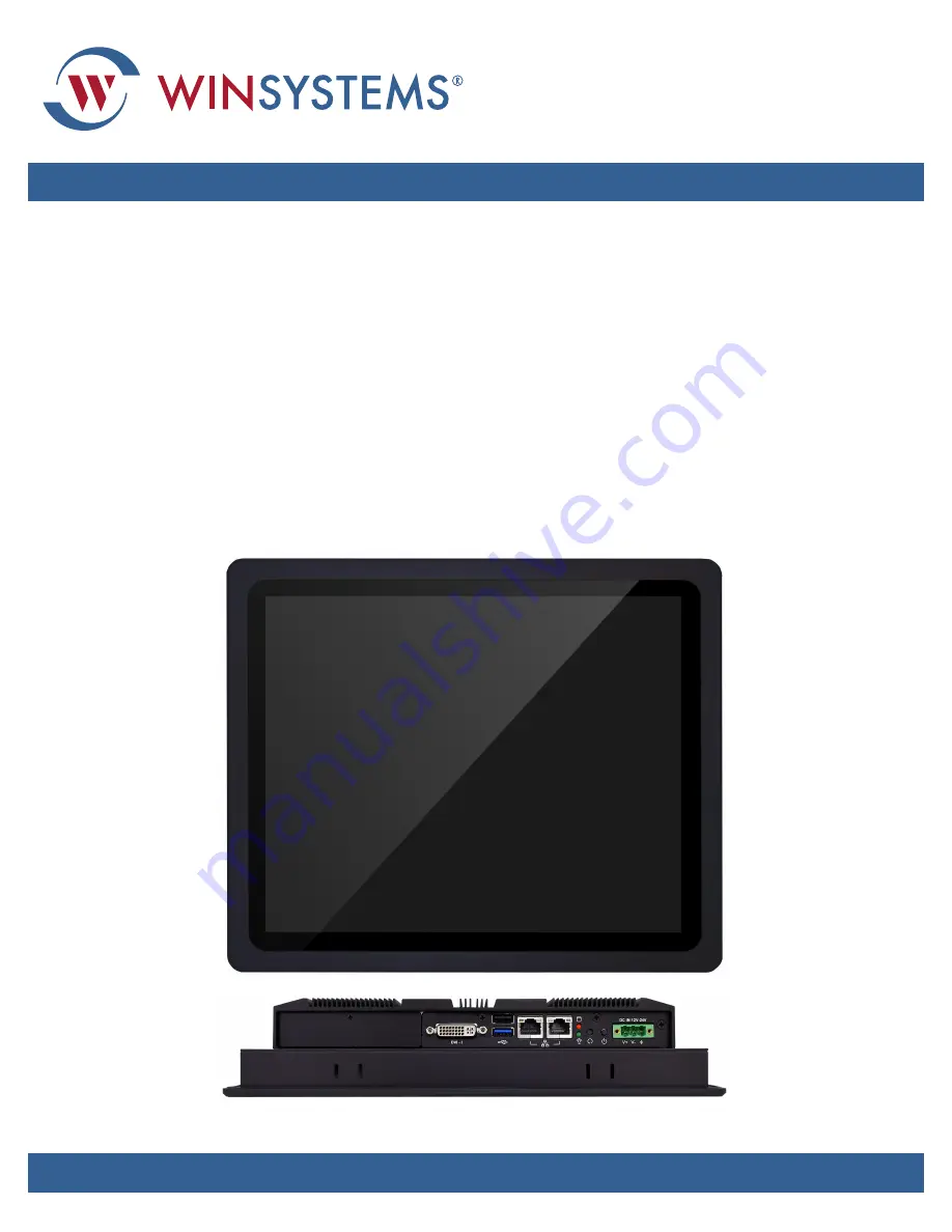
PPC65BP-1x

IP65-Compliant Panel PC with Intel

®

 Atom

E3800 processor and Multi-Touch PCAP

Product Manual

Summary of Contents for PPC65BP-1 Series

Page 1: ...stems Inc 715 Stadium Drive Arlington Texas 76011 817 274 7553 info winsystems com www winsystems com PPC65BP 1x IP65 Compliant Panel PC with Intel Atom E3800 processor and Multi Touch PCAP Product Ma...

Page 2: ...statutory implied or by description regarding the information set forth herein or regarding the freedom of the described devices from patent infringement WINSYSTEMS Inc makes no warranty of merchantab...

Page 3: ...tor and Indicator Locations 10 5 2 1 Power Button 10 5 2 2 Reset Button 10 5 2 3 Power LED and HDD LED 10 6 Specifications 12 6 1 Part Number 12 6 2 Specifications 13 7 Setup and Installation 14 7 1 I...

Page 4: ...1 x 5 Pin Wafer 2mm 32 8 3 8 Touch Panel Connector J21 1 x 5 Pin Header 2 54mm 32 8 3 9 USB Port 3 Connector J22 1 x 4 Pin Wafer 2mm 33 8 3 10 CMOS Setup JP1 33 8 3 11 LCD Panel Inverter ON OFF Signal...

Page 5: ...the system BIOS is lost how can you reset the system 53 10 3 How can the system be configured for AT mode 53 11 Troubleshooting 54 11 1 BIOS Settings 54 11 1 1 Loading the Default Optimal Setting 54...

Page 6: ...Support at 817 274 7553 Monday through Friday between 8 AM and 5 PM Central Standard Time CST Refer to the WinSystems website for other accessories including cable drawings and pinouts that can be use...

Page 7: ...or a SATA cable The PPC65BP 1x series supports operating systems OS such as Linux and Windows 10 Contact an Applications Engineer for details on pre installed operating system options The unit is engi...

Page 8: ...s at High Resolutions 10 point Multi Touch Projective Capacitive PCAP touchscreen Resolution 1024 x 768 1280 x 1024 Connectivity and I O for Embedded Systems 2x Gigabit Ethernet ports 1x USB 2 0 port...

Page 9: ...BIOS Power Power supply 12 V 24 V DC input 3 pin Terminal Block Connector Temperature Specifics Operating temperature 25 C to 70 C 13 F to 158 F Storage temperature 40 C to 85 C 40 F to 185 F relativ...

Page 10: ...top and side views are shown below NOTE See Connecting Power to J16 on page 18 and Connecting Components on page 18 for information on the connectors 5 2 1 Power Button Press the power button to turn...

Page 11: ...65BP 1x LED status Status Power LED HDD LED Off N A N A Working Green Red Bottom view Top view Selectable I O kit USB 2 0 USB 3 1 Gen 1 Gigabit Ethernet Reset button Power button DC in 12 24V via 3 pi...

Page 12: ...cifications and requirements 6 1 Part Number The part number in PPC65BP x a b c format describes the model PPC65BP 1x options See the following table for specifics Side views CompactFlash cover Table...

Page 13: ...Res SXGA 1280 x 1024 Brightness 350 cd m2 Contrast Ratio 1000 1 LCD Size 19 Res SXGA 1280 x 1024 Brightness 350 cd m2 Contrast Ratio 1000 1 Backlight LED type Touch Screen 10 point Multi Touch Projec...

Page 14: ...W 12 V 30 2 W 24 V Consumption Min 10 2 W 12 V 11 5 W 24 V Consumption Max 30 W 12 V 30 5 W 24 V Consumption Min 10 W 12 V 11 8 W 24 V Consumption Max 37 8 W 12 V 38 3 W 24 V Consumption Min 10 W 12...

Page 15: ...7 2 Installing Memory To install memory 1 Remove power from the PPC65BP 1x 2 Remove the screws securing the rear cover and remove the cover 3 Insert memory module into J3 at an angle and then press d...

Page 16: ...lever to the left 4 Secure the HDD to the tray using four M3 x 3 5mm 0 5mm pitch screws 5 Push drive and tray back into PPC65BP 1x 6 Reinstall the HDD slot cover 7 4 Installing CompactFlash and Secur...

Page 17: ...mpactFlash slot cover shown below and remove the cover 3 Insert the CompactFlash or SD card into the applicable socket Both card types can be used at the same time Eject a CompactFlash card by pressin...

Page 18: ...nnector screw Use AWG 22 14 wire Supply voltage between 12 V DC and 24 V DC Make connections according to the following table 7 6 Connecting Components The PPC65BP 1x provides edge connectors for comm...

Page 19: ...ndustrial cabinet using the provided panel mount holes and kits see Panel Mount on page 19 or a VESA compliant adapter plate see VESA Mount on page 21 NOTE To protect the PPC65BP 1x from dust and wate...

Page 20: ...clip into each panel mount hole Table 4 Panel mounting dimensions Part Number A mm 1 B mm 2 C mm 3 D mm 3 Quantity of Kits PPC65BP 10 10 52 5 265 222 8 PPC65BP 12 10 52 289 244 8 PPC65BP 15 7 50 6 36...

Page 21: ...igure above to a maximum of 13 23 kgf cm 11 483 pound inch 7 7 2 VESA Mount The PPC65BP 1x can be installed using a VESA 75x75 100x100 compliant adapter plate Refer to the following figure for dimensi...

Page 22: ...he reset button also resets the unit 7 9 Installing Drivers To obtain drivers see the WinSystems website at www winsystems com 7 10 Watchdog Timer WDT The PPC65BP 1x features an advanced watchdog time...

Page 23: ...ITE 0x81 define WDT_MODE 0x06 WDT Select mode define WDT_MIN 0x07 Minute mode counter define WDT_SEC 0x08 Second mode counter Use port 62 and port 66 to access EC command data static int IBF_Check uns...

Page 24: ...heck outportb EC_CMD EC_CMD_READ IBF_Check outportb EC_DATA address OBF_Check data inportb EC_DATA return data void EC_WDT_Trigger WDT Counter Write_EC WDT_SEC 0x05 if use minute mode Write_EC WDT_MIN...

Page 25: ...on page 54 for usage 8 Configuration This section describes the PPC65BP 1x components and configuration 8 1 Component Layout The PPC65BP 1x provides edge connectors for common external connections se...

Page 26: ...iguration v1 0 www winsystems com Page 26 JP2 JP3 JP1 J1 J3 JP4 SW1 J4 JP5 JP14 J9 J6 J16 J14 J13 J12 J15 J11 J7 J10 JP10 JP13 JP11 JP12 JP8 J8 JP9 JP6 JP7 SW2 J5 J2 Top view J17 J18 J19 J22 J21 J20 J...

Page 27: ...J8 GPIO connector 2 5 pin 2 0 mm page 29 J9 SM Bus connector J10 Battery connector J11 PCI E X 4 slot right angle for audio and COM port signal J12 USB port 0 1 D sub connector Up USB 2 0 Down USB 3 1...

Page 28: ...supports DDR3 DSRAM system memory 1066 MHz or 1333 MHz through this on board SODIMM socket 204 pin Table 7 Jumpers Item Description Reference JP1 Clear CMOS page 33 JP2 Backlight voltage setup page 3...

Page 29: ...Each Ethernet interface includes 10 100 1000 Mb s multispeed full and half duplex operation The following pinout describes the standard RJ45 Ethernet connectors On board Ethernet activity LEDs are bu...

Page 30: ...Pin Reference Pin Function Description 1 TX_D1 Transceive data 2 TX_D1 Transceive data 3 RX_D2 Receive data 4 BI_D3 Bi directional data 5 BI_D3 Bi directional data 6 RX_D2 Receive data 7 BI_D4 Bi dire...

Page 31: ...15 Pin Hirose 1 25mm Layout and Pin Reference Pin Description 1 LCD_ENBLT 2 GND 3 12 V 4 LCD_BLADJ 5 5 V Pin Description Pin Description 1 YAP0 2 YAM0 3 YAP1 4 YAM1 5 YAP2 6 YAM2 7 YAP3 8 YAM3 9 CLKA...

Page 32: ...x 5 Pin Wafer 2mm Layout and Pin Reference 8 3 8 Touch Panel Connector J21 1 x 5 Pin Header 2 54mm Layout and Pin Reference Pin Description 1 LED Hi Green LED Low Orange LED 2 LED Hi Orange LED Low Gr...

Page 33: ...r ON OFF Signal Setup JP2 The following table contains descriptions of the signal setup for different jumpers installed Layout and Pin Reference Pin Description 1 5 V 2 USB_D3 3 USB_D3 4 GND 1 Jumper...

Page 34: ...in Reference 8 3 14 GPIO Power Selection JP7 This jumper configures the on board programmable 8 bit Digital I O interface Layout and Pin Reference Jumper Description 1 3 3 3V TFT LCD default 3 5 5 V T...

Page 35: ...onnections Layout and Pin Reference Additional Information This connection is a JST B4B PH K S LF SN Mating Connector JST PHR 4 8 3 16 LPC Debug Port Pin Assignment JP9 Layout and Pin Reference Pin De...

Page 36: ...JP11 Layout and Pin Reference 8 3 19 COM4 Pin 9 Function Setup JP12 Layout and Pin Reference Jumper Description 1 2 5 V output 3 4 RI function default 5 6 12 V output 1 2 3 4 5 6 Jumper Description 1...

Page 37: ...ON ON 800 x 600 18 bit Single OFF ON ON ON 1024 x768 18 bit Single ON OFF ON ON 1024 x768 24 bit Single OFF OFF ON ON 1280 x 768 18 bit Single ON ON OFF ON 1280 x 800 18 bit Single OFF ON OFF ON 1280...

Page 38: ...formation stored in the CMOS memory If during startup an error is detected or the CMOS parameters need to be initially defined the diagnostic program prompts the user to enter the SETUP program Some e...

Page 39: ...asily called up from any menu by pressing F1 The Help screen lists all the possible keys to use and the selections for the highlighted item Press Esc to exit the Help screen 9 3 Navigating the Menus U...

Page 40: ...ht the month day or year by pressing the Enter key until the desired value is highlighted with a square block Use the keys to change the highlighted value or enter the time using the number keys Syste...

Page 41: ...tive Processor Cores Sets the number of cores to enable in each processor package Choices All default 1 Intel Virtualization Cores Enables disables cores When enabled a VMM can utilize the additional...

Page 42: ...roller 1 Enables disables LAN controller 1 PCI Express Port 2 Choices Disabled Enabled default Launch Legacy PXE Rom Enables disables the launch of the Legacy PXE Rom Disable Not Launch Rom Enabled Fo...

Page 43: ...DVMT 5 0 Total Graphics Memory sized used by the Internal Graphic Device Choices 128MB 256MB default Max Touch Pad Enables disables touch pad Choices Enabled default Disabled Primary IGFX Boot Displa...

Page 44: ...oices Enable default Disable Speed Sets configuration PCIe speed Choices Auto default Gen1 Gen2 PCI Express Configuration Port 2 Enables disables port 2 Choices Enabled default Disabled Speed Sets con...

Page 45: ...port Enables disables XHCI Controller Legacy support Choices Enabled Disabled default XHCI Hand off This is a workaround for operating systems OS without XHCI hand off support The XHCI ownership chang...

Page 46: ...i PCIE Choices Enable default Disable USB Port 3 Enable Disable USB Port 3 The USB port as USB HUB have 2 USB Port in external cart Choices Enable default Disable Power Control Configuration Use the P...

Page 47: ...IRQ 4 Choices Disabled Enabled default Interface Set present UART mode RS232 RS485 RS485 RS422 Choices RS232 default RS485 HALF DUPLEX RS485 422 FULL DUPLEX Termination Control Set Termination Contro...

Page 48: ...Serial Port Enable or Disable Serial Port COM IO 248H IRQ 11 Choices Disabled Enabled default Watch Dog Timer Enable or Disable Watch Dog Timer Choices Disabled default Enabled Timer Unit Watch Dog Ti...

Page 49: ...Security Status screen to set passwords Password Check Mode Setup check password when enter setup screen Power On check password every time the system powers on Choices Setup default Power On Administ...

Page 50: ...activation key 65535 0xFFFF means indefinite waiting Choices Default 5 Bootup NumLock state Select the keyboard NumLock state Choices On default Off Post Report Post Report Support Enabled Disabled Ch...

Page 51: ...TPONED execute the trap during legacy boot Choices Immediate default Postponed Storage Controls the of execution of UEFI and Legacy Storage OpROM Choices Do not launch default UEFI only Legacy only Fu...

Page 52: ...PPC65BP 1x BIOS Settings v1 0 www winsystems com Page 52 Save and Exit Use the Save Exit screen to save changes discard changes restore defaults and other similar commands as listed...

Page 53: ...be configured for AT mode The default setting is ATX mode This mode requires the power button to be pressed to turn the system on By configuring SW2 port 1 and restarting the system you can configure...

Page 54: ...equence to configure a stable BIOS configuration that can be woken NOTE Although you can access the BIOS by pressing Esc instead of Del Del is used in the following procedures 11 1 1 Loading the Defau...

Page 55: ...rt of the PPC65BP 1x and apply power to the board 4 Boot to EFI Shell mode 5 At the prompt enter the command fs0 to change to the root directory of the USB drive 6 At the root directory of the USB dri...

Page 56: ...moved from the system before making or breaking any connections I O Connections OFF I O Connections should also be off before connecting them to the embedded computer modules or any I O cards Connecti...

Page 57: ...e Digital for revisions Check Pinouts Always check the pinout and connector locations in the manual before plugging in a cable Many I O modules have identical headers for different functions and plugg...

Page 58: ...PPC65BP 1x v1 0 www winsystems com Page 58 Appendix B Mechanical Drawings PPC65BP 10 Dimensions...

Page 59: ...PPC65BP 1x v1 0 www winsystems com Page 59 PPC65BP 12 Dimensions...

Page 60: ...PPC65BP 1x v1 0 www winsystems com Page 60 PPC65BP 15 Dimensions...

Page 61: ...PPC65BP 1x v1 0 www winsystems com Page 61 PPC65BP 17 Dimensions...

Page 62: ...PPC65BP 1x v1 0 www winsystems com Page 62 PPC65BP 19 Dimensions...

Page 63: ...hall remain vested in WinSystems until complete payment is made by Customer Title to any Software shall remain vested in WinSystems or WinSystems licensor from whom WinSystems has obtained marketing r...

Reviews: