background image


This Document Contains Confidential & Proprietary Information


Winegard Company 

 3111 Kirkwood St. 

 Burlington, IA 52601 

 877-704-1112 

Printed in USA ©2011 Winegard Company 

www.winegard.com


7451014 | Rev1 12-13 


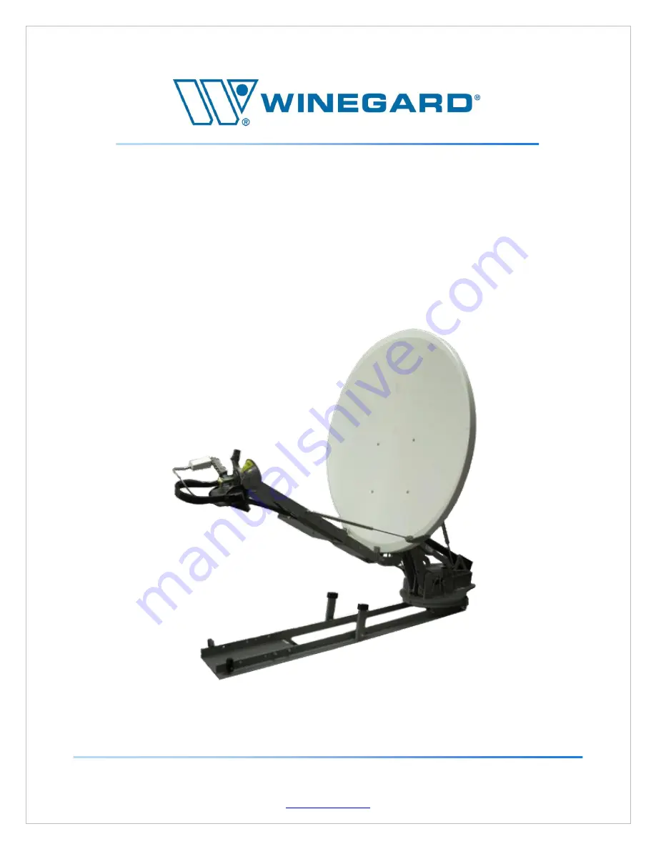
WINEGARD 2-WAY SATELLITE 

INTERNET SYSTEM 

PRODUCT MANUAL 


Summary of Contents for WX980

Page 1: ...idential Proprietary Information Winegard Company 3111 Kirkwood St Burlington IA 52601 877 704 1112 Printed in USA 2011 Winegard Company www winegard com 7451014 Rev1 12 13 WINEGARD 2 WAY SATELLITE INTERNET SYSTEM PRODUCT MANUAL ...

Page 2: ...nicians All companies and service personnel using this document must have a signed non disclosure agreement on file with Winegard Company For information on how to obtain a non disclosure agreement from Winegard Company please contact either support winegard com or call 877 704 1112 ...

Page 3: ...lation Information 17 6 CONTROLLER DESCRIPTION CONFIGURATION 22 6 1 Front Panel Connections Interfaces 23 6 2 Rear Panel Connections 24 6 3 Main Menu Interface Screen 25 6 4 Configuration 26 6 6 Advanced User Data 50 7 OPERATION 55 7 1 Find Satellite 55 7 2 Stowing 59 8 SERVICE AND TROUBLESHOOTING 61 8 1 Theory Of Operation 61 8 2 Global Procedures 63 8 3 Maintenance Procedures 65 8 4 Calibration ...

Page 4: ...tions 79 9 REFERENCE MATERIALS 80 9 1 Upper and Lower case TRK 80 9 2 Null Modem 80 9 3 On Screen Keypad Windows CE 80 9 4 Wiring Diagram 81 10 WX1200 TECHNICAL SPECIFICATIONS 82 11 WX980 TECHNICAL SPECIFICATIONS 75 12 INDOOR CONTROL UNIT TECHNICAL SPECIFICATIONS 77 13 CE DECLARATION OF CONFORMITY 78 ...

Page 5: ...Automated Machinery The outdoor antenna system may start moving anytime the indoor controller is powered on Lockout tag out procedures should be followed before servicing Servicing should only be completed by trained authorized personnel There are no user serviceable parts inside the unit Warning Bodily Injury Hazard The antenna assembly may rotate around the mount base Keep fingers and other body...

Page 6: ...nch Hazard Bodily Injury Hazard Antenna support and lift mechanism Keep hands and other body parts away Warning Pinch Hazard Bodily Injury Hazard Rotating feed horn polarizer mechanism Keep hands and other body parts away ...

Page 7: ...m Above Bodily Injury Hazard Skew polarizer assembly feed arms and mounting brackets Keep hands and other body parts away Warning Pinch Hazard Crush from Above Bodily Injury Hazard Antenna support brackets Keep hands and other body parts away ...

Page 8: ...P a g e 8 Warning Pinch Hazard Crush from Above Bodily Injury Hazard Antenna support brackets Keep hands and other body parts away ...

Page 9: ...P a g e 9 2 1 How To 1 Unpack system and remove pallet 2 Unlatch the lid hold down brackets on either end of the skid as shown below ...

Page 10: ...P a g e 10 3 Open lids on both sides as shown below ...

Page 11: ...the skid before making any movements Open the IDU case remove the controller and make the appropriate connections Use the case to store the latch straps but do not store the case inside the skid at any time except when stowing the unit for transportation ...

Page 12: ...s shown below 6 Disconnect the three cable connectors red yellow and blue from the side of the drum as shown below using the provided wrench prior to unrolling the cables Reconnect all three cables after cable has been reeled out to a sufficient length ...

Page 13: ...ce and 2 this device must accept any interference received including interference that may cause undesired operation Antenna Systems WX1200 WX980 Indoor Control Units 7750188 7750190 CE Marking The following model s have been tested and found to be in compliance with all applicable EC directives including EMC Directive 2004 108 EC Low Voltage Directive 2006 95 EC See Declaration of Conformity in S...

Page 14: ...f It does not include the RF components supplied by the user such as the BUC and LNB Interchangeable words in the industry ODU Antenna Electronics Antenna Winegard 2 Way Antenna Includes all physical components of the system except the IDU Motors hardware links ODU Reflector and RF Electronics are all components of the antenna Interchangeable words in the industry Antenna Mount System Winegard 2 W...

Page 15: ... intended to be mounted on the roof of a vehicle or mobile platform The WX antenna system consist of a high wind resistant mechanical antenna Out Door Unit ODU and all wiring and motors required to point the system using the Winegard 2 Way Controller The model numbers for the appropriate controllers are 7750188 TNC connector and 7750190 F connector The WX antennas are available in either 0 98 WX98...

Page 16: ...ntenna to the vehicle or mobile structure Hole patterns for installation are available on the dimension documents at the end of this manual 11 Feed Arms Houses the Universal BUC mounting plate which can be used to mount the user supplied BUC The BUC can have a maximum size of 12 00 L x 7 75 W x 5 5 H and maximum weight of 15 lbs 12 Skew Assembly Houses the Skew drive motor Feed assembly user suppl...

Page 17: ...mounting point on the vehicle roof or mobile platform Use 8 3 8 inch x 1 inch 10 mm x 25 mm Grade 8 bolts with washers and appropriate lock nut 2 Wiring Bulkhead TX and RX cables are F connector terminated and go directly to the modem Satellite In Rx and Satellite Out Tx ports The ODU power communication cable is TNC or F connector terminated and connects the antenna to the Winegard 2 Way Controll...

Page 18: ...P a g e 18 3 Max Clearances The Max Horizontal and Vertical clearances should be considered when deciding where to install the antenna ...

Page 19: ...P a g e 19 ...

Page 20: ...he OPT1038 skid option please follow the guidelines in the drawing below to pre point the skid system prior to deployment depending on the necessary elevation clearance for the location where the system is being deployed Section A 0 to 20 degrees Section B 21 to 120 degrees Section C 121 to 180 degrees ...

Page 21: ... technician stations the antenna so that the relative location of the satellite to the antenna falls within Section C of the drawing then the system would be unable to find the satellite since the minimum elevation angle at Section C is 20 degrees In another example if the elevation angle is 12 degrees then the field personnel would need to station the antenna so that the relative location of the ...

Page 22: ...with several leading modems in the industry such as iDirect s Infinity and Evolution modems HughesNet HX HN and DW modems Gilat Skyedge I and Skyedge II modems Comtech and Comtech ViperSat modems as well as many others The controller is simple to upgrade using a Flash drive and the built in touch screen The Indoor Control Unit IDU is rack mountable It fits in a standard 19 inch rack and is 2 units...

Page 23: ... Thumb drive but can also host a keyboard or mouse One additional USB Host Connector is available on the rear panel which is described in page 14 of this manual Information about updating the software on the controller can be found on section 2 6 1 7 Update screen on page 44 3 Touch Screen The Touch Screen is the main interface to the controller It is a fully interactive color screen which provide...

Page 24: ...VAC power cord See section 4 7 for power cord specifications The power cord must be connected to a grounded socket outlet protected by a 20 amp fuse or circuit breaker The power cord is the disconnecting device The socket outlet for the power cord shall be installed near the equipment and be easily accessible If the IDU is installed in a rack accessibility must be provided to the power cord or to ...

Page 25: ...uration of the system as well as the Advanced User Data section wrench to see live data network configuration and firmware update screen At the bottom of the screen you can see the Signal Strength as well as the Compass Heading and Mode The currently running version of the software is listed below the Authorized Installer and Advanced User Data icons Deployment and Stow buttons are available in th...

Page 26: ...Configuration process the modem type will be selected at that time the controller will attempt to interface with the modem If the Network settings are incorrect the controller will fail this attempt As mentioned earlier in the Scope of this manual description of screens not related to the actual process being described will not be undertaken at this stage How to Configure Network Settings 1 Tap th...

Page 27: ...t that the display at the top of this screen states NETWORK SETUP DHCP If not then tap on the DHCP button on the bottom left hand corner of the screen b IP Mask Gateway and DNS information being distributed by the modem should populate the main screen after a few seconds c Once DHCP data is present and verified proceed to step 10 9 STATIC a If the modem with which this controller is being configur...

Page 28: ... one character per tap 10 Once all network configuration information has been entered and verified tap on the MAIN MENU button at the bottom of the NETWORK SETUP screen to exit to the main menu 11 Configuration of the controller can now proceed on section 6 4 2 of this manual ...

Page 29: ...enna or perform calibrations and the second section is primarily centered around the modem and service parameters for the search How to Configure the Controller 1 Tap the Authorized Installer Menu Icon in the Main Menu 2 The controller will enter the Installation menu section The INSTALLATION MENU screen asks if you want to select AUTHORIZED INSTALLER for configuration purposes or MAIN MENU to bac...

Page 30: ...After entry of the pass code 1234 press the NEXT button to continue the configuration 4 ANTENNA SETUP screen The next screen that appears is the ANTENNA SETUP screen This step of the configuration asks if you want to perform movement of the antenna for installation purposes It is not necessary to perform antenna movement to configure the controller a If you select NO you will be taken to the EMERG...

Page 31: ... screen back to the main menu without changes to you jogging movements being nulled The step rates available here are 1 5 1 5 10 25 and 45 degrees per button selection Signal Strength is also displayed here for pointing purposes 5 EMERGENCY screen If you have selected NO on the ANTENNA SETUP screen then you will move forward to the EMERGENCY movement screen This screen asks if you want to perform ...

Page 32: ...ment of the antenna intended for Emergency stowing if for some reason the system is stowing in the incorrect azimuth location For this reason the system will allow unsafe movements of the Elevation actuator in order to stow a system in a position where the system considers it unsafe The step rates available here are 1 5 1 5 10 25 and 45 degrees per button selection ...

Page 33: ...actory prior to shipping a If you select No you will be taken to the CALIBRATE COMPASS screen on item 7 b If you select Yes the following screen will appear i If NEXT is selected the controller will exit the Calibration without any movement and proceed to the next step in the configuration described on item 7 ii If you select GO then the Calibration will begin ...

Page 34: ...s then the system completed a successful calibration Tapping the NEXT button will move the configuration to the next step on item 7 7 CALIBRATE COMPASS screen After the CALIBRATION screen the system continues to the HEADING screen and will display one of two screens depending on the currently selected COMPASS MODE Since a compass Verification and Calibration will be performed after the configurati...

Page 35: ...P a g e 35 b If the system is in Compass mode then the following screen will appear Select SKIP to move to the COMPASS HEADING screen where you will select NEXT to continue to step 8 ...

Page 36: ...ode iDirect Only In Inclined Orbit Search Mode once the satellite acquisition has finished the controller will go into a re peaking mode period for 24 hours During this period and at the interval set in the Inclined Orbit parameters the controller will analyze the signal strength and re peak the antenna if the signal has dropped beyond a specific threshold value The location of the beginning of th...

Page 37: ...mtech Vipersat There are three basic modem selections that require different sets of information to configure the controller 1 Generic Primarily used for troubleshooting Satellite Longitude Carrier Frequency Symbol Rate Rx Polarization 2 HughesNet Self Configuring 3 Others iDirect Nera Spacenet Comtech Comtech Vipersat LinkStar Satellite Longitude Rx Polarization For the purpose of this manual the...

Page 38: ...uest of the modem to ensure that it is also locked onto its corresponding carrier This search is good for verification of satellite lock if perhaps the modem has the wrong carrier information on it This search mode has a smaller search window and moves the antenna across the sky at a faster rate For the purpose of this manual select MODEM and the screens associated with that selection will be desc...

Page 39: ...n Alpha values toggle when you tap on them When the correct Longitude Hemisphere and Polarization are selected press the DONE button to continue the configuration c The SEARCH SETTINGS screen asks if you would like to make changes to the default Search Window settings The default search window settings for MODEM are Window Width 90 Deg Window Height 10 Deg Elevation Spacing 5 Deg Azimuth Speed 5 D...

Page 40: ...hanges by pressing OK Remember that AUTO PEAKING was originally disabled and pressing YES on the previous screen enabled it so the OK button here merely continues with the configuration with Auto Peaking enabled NOTE AUTO PEAK DOES NOT TURN OFF THE TRANSMITTER The goal of Auto Peaking is to examine the SNR changes over time and adjust the antenna pointing to ensure optimal signal at all times Beca...

Page 41: ...tion selections to the configuration memory and return the system back to the Main Screen The Find Satellite button will be available if the system is in the stowed position and ready for deployment Selecting NO here will bring up a screen stating that Satellite configuration has been cancelled The only option after selecting no is to press OK which will return the controller to the INSTALLATION M...

Page 42: ...ion notes The controller is now configured to work with the iDirect modem selected for this install As stated earlier prior to deployment the installer should Verify and Calibrate Compass heading which is covered in the next section ...

Page 43: ...tructure Calibration of these antennas can be accomplished by simply rotating the antenna on its own mounting axis and it is therefore an autonomous process The Winegard 2 Way Controller offers two modes to operate the system Compass Mode which derives its heading from the compass built into the ODU and Fixed Heading Mode which derives its heading from a user defined input 6 5 1 HEADING screen The...

Page 44: ...t a Compass Calibration is currently required and the True Heading display shows a very accurate heading 2 HEADING screen Fixed Heading Mode Notice the CALIB button is NOT enabled and the mode next to the MODE toggle button shows FIXED The wording above the MODE button states that the system is in Fixed Mode and requests to select the direction of the stowed antenna using the compass to the right ...

Page 45: ...mpass Mode and choose a path below A If the controller is currently set to COMPASS mode proceed to step 3 B If the controller is currently set to FIXED Heading mode then tap the MODE button to switch the controller to Compass Mode then proceed to step 3 3 As long as the controller is in COMPASS mode the CALIB button will be available Tap the CALIB button to enter Calibration mode ...

Page 46: ... beginning a calibration use a handheld compass to determine the direction the reflector faces when in the stowed position Most of the time that direction will be facing towards the back of the vehicle i If the heading displayed is within 15 degrees of the actual heading from your handheld compass there is no need to calibrate the compass Press SKIP to exit the calibration and move to step 5 ii If...

Page 47: ...es of the value sampled from the handheld compass then compass calibration is complete Proceed to step 5 6 5 3 FIXED Heading There will be times when using the compass may not be the best choice Some instances where you may want to override the compass include If the compass is not calibrated and the resources to calibrate it are not available or time does not permit the full calibration For troub...

Page 48: ...proceed to step 3 3 As long as the controller is in FIXED mode the sections of the compass above and to the right of the compass screen will be available to manually set a heading Tap on the direction the face of the reflector is facing when the system is stowed This will set the True and Rough headings to the correct heading Alternately you can also tap on the true heading display and enter an ex...

Page 49: ... calculation of the target satellite vector 4 After the correct direction is set press the DONE button to return to the Main Screen Compass override is complete 5 If compass override needs to be disabled simply return to the HEADING screen and change the MODE from FIXED to COMPASS ...

Page 50: ...ta screens pressing the Main Menu will take you out of the Advanced User Data section and return to the Main Screen 6 6 1 Accessing the Advanced User Data 1 Tapping the Wrench Icon in the Main Menu enters the display into the Advanced User Data screens 2 POSITION STATISTICS screen The POSITION STATISTICS screen is the first screen available in the Advanced User Data section It displays live Pitch ...

Page 51: ...he display here would change to Saved and the Edit button would be available to override coordinates Select NEXT to advance 4 CALIBRATE THE MOUNT screen As stated on this screen Calibration is not required since the system is calibrated at the factory but can be performed any time without any danger of problems The new calibration data will simply override the older data Please ensure that the sys...

Page 52: ...guration section on page 16 Select NEXT to advance 6 VERSIONS screen The VERSIONS screen displays current software for both the Controller IDU and Outdoor Electronics ODU Please see the Reference section for listing of software versions and System ID information Select NEXT to advance ...

Page 53: ...s time a RESET CONFIG Selecting to RESET CONFIG button will take the controller into the screen above The configuration file contains the parameters set during the Configuration section of this manual RESET will delete all configuration parameters from the configuration file and rebuild it using factory values REPAIR erases only the parameters that are not absolutely required to point the antenna ...

Page 54: ...pdate by selecting NEXT This takes the controller back to the Main Screen Selecting GO will cause the controller to look for a version of the Firmware on a USB Flash drive connected to the Controller host USB port If a newer version of the firmware is found on the drive the controller will automatically copy the new versions and flash all pertinent components as part of the Update process Do not i...

Page 55: ...arrier is not present The Stow button is only available when the system is not in a stowed position etc Always ensure that compass heading and mode are accurate before performing a search 7 1 Find Satellite 1 When the controller has booted to the Main screen tap the Find Satellite button to deploy the system and acquire the satellite carrier 2 Before making any movements the controller will first ...

Page 56: ...P a g e 56 ...

Page 57: ...antenna deploying to the calculated coordinates The controller will move and test the calculated location for a modem lock If a lock is found at that location the controller will begin to peak the carrier 4 If no lock is detected when at the calculated location the controller will begin searching the target window The screen will read Fast Search ...

Page 58: ... where it received a lock status and is attempting to find the lock again 6 Once a Lock is found the Controller will move to the Peaking stage The controller will first peak the antenna in Azimuth and then in Elevation before stopping all movement 7 When the antenna is completely peaked the controller will return to the Main Menu screen 8 The acquisition process is complete ...

Page 59: ...the antenna is as simple as tapping the STOW ANTENNA button 2 The controller will first ask if you wish to stow the antenna in order to verify that your request for stow was not an error in input To stow the antenna tap the YES button ...

Page 60: ...ff the Transmitter Once a reply has been received that the Transmitter is offline the controller will begin moving the antenna back into the stowed position 4 When the antenna is finished stowing the screen will return to the Main Menu with the Find Satellite button enabled 5 The stow process is complete ...

Page 61: ...cables The RG6 cables are terminated with environmentally sealed F connectors As mentioned above the modem supplies the DC voltage necessary to power the LNB The IDU supplies 48 volts DC to the antenna s OutDoor Unit ODU through an RG6 or equivalent cable terminated with TNC connectors Communication between the IDU and the ODU are carried over the antenna s power cable utilizing Bluetooth Protocol...

Page 62: ...eral safety features built into the antenna system These features automatically stow the antenna if certain criteria are met These include loss of receive signal lock detected motion pitch roll velocity as well as turning the power off to the system by pressing the power button on the IDU 8 1 7 Functional Block Diagram Legend Ethernet GPS DC Wiring Harness Control RF Wiring Harness Modem Rx Tx Pow...

Page 63: ...ith these operations prior to entering other functional sections of the manual 8 2 1 Accessing trk prompt Debug mode The debug prompt allows interaction with the controller using a command line type interface In the debug prompt you can perform any function you would using the GUI but it is friendlier to technical personnel who may feel more familiar and comfortable with this type of interface 1 T...

Page 64: ... The ID is stored in the Outdoor Control Unit This System ID is important for troubleshooting purposes and can be viewed on the VERSIONS screen in the GUI The information below describes how to obtain the System ID 1 Turn the controller on 2 Allow the controller to boot to the Main Menu screen 3 Click on the Wrench icon on the upper right hand corner of the screen 4 Navigate through the screens un...

Page 65: ...log into the site and download software and other related documents manuals and white papers If an account is required please go to the support site and request an account or contact support at 877 704 1112 1 GUI UPDATE Screen The UPDATE NOW button can be found on the Winegard controller s Update screen of the Advanced User Data section of the pointing software This process automatically updates t...

Page 66: ...olves systems that may require periodic calibration These include setting the antenna system s home position and calibration of the on board compass Both of these procedures can be accomplished using either the USB keyboard or the Indoor Unit IDU in normal operation 8 4 1 Calibration of the Skew Home Position zero degree skew This procedure should be performed if the antenna does not return to the...

Page 67: ...is value may be different depending on model and skew configuration e If the system rotated past the zero degree skew position during skew motor calibration then this value is too large f If the system did not reach the zero degree position during skew motor calibration then this value is too small 8 Type the new value into the IDU and press enter a Start with small value changes b To increase the...

Page 68: ... unit is aligned skip to step 6 c At the DC prompt type p 0 500 and press enter This will rotate the azimuth motor clockwise past the magnetic sensor d At the DC prompt enter the command p 0 100 and press enter This will rotate the azimuth counterclockwise back towards the center of the tray e Continue to rotate the azimuth towards the center It may be necessary to decrease the amount of travel by...

Page 69: ...s below b The command for the following example would be mount 0 5 0 4 c The IDU will display the message Is the antenna stowed with p pitch r roll y n d Selecting n will cancel the calibration e Selecting y will display the message Calibration Successful 5 The pitch and roll should be verified Type att and press return a The IDU should now display the ATT prompt 6 Type att and press return a Valu...

Page 70: ... the left side of the system looking from the rear is higher than the right side the amount of roll is a positive value Roll In this example the left side of the dish is lower than the right side The roll is 0 4 degrees ...

Page 71: ...late proper azimuth from heading info Move to center of search window and initiate search Adjust the center of the search window and skew setting based on pitch and roll Get polarization from the config file Get stored satellite longitude from the config file Modem Lock Peak antenna on RX signal Return to Main Menu Increase search window and adjust search speed slow down NO YES ...

Page 72: ...securely fastened The LNB sticks out from the end of the dish when the antenna is stowed Disconnect the RX LNB cable There should be between 11 to 18 volts DC on the cable Stow the dish and turn the system off Power cycle the modem Verify that the system is searching for the correct satellite During the search the satellite longitude is displayed System stops during the GPS portion of the Initiali...

Page 73: ...ng Sequence Needed message appears on the IDU screen OR Dish raises but will not skew or move in azimuth This may happen when calibrating the motors or normal operation This will happen if the antenna loses power while moving or a possible motor fault Try and perform a motor calibration first If a motor calibration does not clear the error enter the debug menus and try to move the motors individua...

Page 74: ...case for velocity commands DC Stay clear of the system during all system movements Typing s and pressing enter at any time from the debug menus MOTOR DC and HOME will stop all motors There are 3 major types of motor commands Each is described below 8 7 1 Angular Movement The first type of movement is an angular movement command that is done from the MOTOR menu Movements are given using angular com...

Page 75: ...gle 45 00 MOTOR a AZ 44 99 wrap 44 99 EL 29 91 SK 0 04 MOTOR The skew motor operates in the same manor 8 7 2 Positional Movement The second type of movement command is called positional movement The position is based on the number of individual steps per revolution motor pulse counts This position is reset when the system performs a motor calibration homing routine This command is entered from the...

Page 76: ...ll move in azimuth and skew regardless of what the elevation is Make sure the system is at a safe elevation before attempting to move the azimuth or skew motors Stay clear of the entire system during movement commands Caution The elevation will raise and lower its full range regardless of the azimuth and skew position This means it is possible to lower the antenna on either side of the LNB landing...

Page 77: ... a safe elevation before attempting to move the azimuth or skew motors Stay clear of the entire system during movement commands Caution The elevation will raise and lower its full range regardless of the azimuth and skew position This means it is possible to lower the antenna on either side of the LNB landing ramp possibly causing damage to the antenna mount or surrounding equipment Caution Once t...

Page 78: ...ate counterclockwise until it senses the magnetic sensor The azimuth will then return to zero degrees The elevation actuator will then lower the dish until it hits the hard stop The elevation actuator may clutch several times This is normal and does not cause any damage Each axis can be calibrated homed individually In order to calibrate the skew and azimuth motors the system must be at or above a...

Page 79: ...vices Found bt inq Inquiry 5 Seconds 1 Devices Found 0800172C0D32 WCS 000000 3111 Remote Name 0800172C0D32 WCS Tracker Saving Remote Addr 0800172C0D32 Success bt i Release Link BT No Connection Req Establish Success Link Indicator Success bt 8 8 2 Changing the iDirect Default Password The iDirect password can be changed in the debug prompt 1 Enter the debug menus as described in the global procedu...

Page 80: ...parts of this document This replaces the need for a USB keyboard 9 3 On Screen Keypad Windows CE The touch screen keypad can be activated and used instead of a USB keyboard In order to activate the onscreen keypad the system must be running Windows CE 1 Turn the system on by pressing the button on the IDU a A progress bar will scroll across the bottom of the screen b The screen will flash white an...

Page 81: ...P a g e 81 9 4 Wiring Diagram User Supplied Device ...

Page 82: ...84 13 150 lbs Approx Mechanical Range of Motion Azimuth Elevation Polarization Speed Azimuth Elevation Acquisition Time Motors Azimuth Elevation Polarization 375 5 to 100 90 7 5 per second 4 6 per second 2 min typical fixed heading 24V Brushless DC 24V Linear Actuator 24V Brushless DC RF TX Interface RX Interface Frequency Range RX TX Gain Midband RX TX VSWR RX and TX Beamwidth RX TX 3ft Neoprene ...

Page 83: ... to 50 C 58 F to 176 F 50 C to 80 C 8 deep 8 lbs cu ft Electrical Outdoor Unit 48VDC 3 5A Use Only Winegard Indoor Controller Model 7750188 or 775019089 11 WX980 Technical Specifications General Information Reflector Type Focus BUC Polarization Mount Geometry 0 98 M Prodelin Glass Fiber Reinforced Polyester SMC Offset Feed 15 lbs 12 L x 7 75 W x 5 5 H Cross Pole Elevation Over Azimuth Dimensions S...

Page 84: ...ation Isolation port to port RX TX 3ft Neoprene Jacketed Flexible Waveguide WR75 Flange WR75 Flange 10 95 12 75 GHz 13 75 14 5 GHz 39 8 dBi 41 3 dBi 1 3 1 1 8 3 dB 3 3 10 dB 1 5 3 dB 2 8 10 dB FCC Part 25 209 46K 20 EL 43K 30 EL 30 dB Minimum 35 dB 80 dB Environmental Ingress Protection Rating Wind Operational Survival Deployed Survival Stowed Temperature Operational Survival Snow Load IP65 50 MPH...

Page 85: ...19in x 3 5in x 13 5in 7 5lbs 4 F to 127 F 20 C to 50 C 58 F to 176 F 50 C to 80 C Electrical Power Supply Input Fuse AC Power Cord US Type Voltage Plug Rating Certification Standard European Power Cord supplied by installer 100 240VAC 50 60Hz 5A 5A 32V Fast Acting Type ATF Located on rear panel of IDU Winegard P N 2320020 Longwell LP 31 NEMA1 15P 120VAC 60Hz 15A 125VAC UL UL817 Winegard P N 232007...

Page 86: ...P a g e 78 13 CE Declaration of Conformity ...

Reviews: