WiMo ACOM2000SW, Manual
The WiMo ACOM2000SW manual is available for free download at manualshive.com. This comprehensive manual provides detailed instructions and information on operating and optimizing the ACOM2000SW antenna switch. Master the functionalities of this powerful device with our user-friendly manual, ensuring a seamless and hassle-free experience.
Share
Download


Reviews:
No comments
Related manuals for ACOM2000SW

7 617 495 213
Brand: Blaupunkt Pages: 12

Dummy Load V2
Brand: Pacific Antenna Pages: 5

C27-5S-BTW
Brand: HiBoost Pages: 15

40M4LLDD
Brand: M2 Antenna Systems Pages: 14

TEW-OA14DK
Brand: TRENDnet Pages: 2

ETS-Lindgren 3106B
Brand: ESCO Technologies Pages: 79

TL-ANT2406A
Brand: TP-Link Pages: 2
TL-ANT2409A
Brand: TP-Link Pages: 6
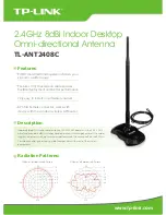
TL-ANT2408C
Brand: TP-Link Pages: 2

SNIPE PLATINUM
Brand: SELFSAT Pages: 67

GP 87-108 LB
Brand: Sirio Antenne Pages: 4

ISD710
Brand: iBeam Pages: 2

Hydrawise HCC
Brand: Hunter Pages: 55

RB31
Brand: Vaisala Pages: 30

MFJ-1754
Brand: MFJ Enterprises Pages: 5

airGrid M2 HP AG-HP-2G16
Brand: Ubiquiti Pages: 24

50LFA10
Brand: EAntenna Pages: 22

OBU-4041
Brand: KAPSCH Pages: 24


