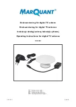
background image

50LFA10

50LFA10

17,75m

Peso: 30 Kg.
Max. Potencia: 10 kW

Yagi Antenna

Yagi Antenna

Thank you for choosing EAntenna.

 
All our products are manufactured and developed with the best materials on the market, to offer the best qualities and guarantees to our 
customers.

 The LFA antennas have an input impedance of 50 Ohm in the antenna, so no coupling is necessary. The loop is at the same time a coupling 
system and director element and this presents many advantages when modeling.

The 'real' impedance of each LFA varies greatly. But, the impedance presented at the antenna entry point is always 50 Ohm. Therefore, there 
is no limitation on the results of any optimization tool achieved with a single input impedance, but it manages to change the width and length of 
the loop keeping the impedance at 50 Ohm. This feature is very important to ensure good performance, bandwidth and low SWR in the 
antenna.

This additional flexibility also allows more lateral lobes to be suppressed and a better front-to-back (F / B) ratio compared to traditional Yagis. 
With time it is possible to achieve an excellent balance between design, F/B, gain and bandwidth.

Additionally, the proximity of the loop and the antenna entry point make the LFA less susceptible to noise and static nearby. In addition, the low 
level of the LFA lateral lobes provides a winning formula for an antenna with super low noise!

We detail the materials used, for their best use and assembly. All the fittings are made of stainless steel and the aluminum is made of T6061 or 
T6063 alloy, known as Duralumin that offers the best conditions to be weatherproof, the force of the wind and the best conductivity. The 
plastics used, are Polyamide and offer the best hardness and durability for years and years.
We offer warranty on operation, and warranty on hardware, delivering the hardware kit with some additional pieces for possible losses or 
forced breaks. In addition, we offer Allen keys and fixed mounting elements.
In the following pages you can see detailed graphics of the parts.
 

17800.06-10

Rev. V1.4 - 20/11/2020

Summary of Contents for 50LFA10

Page 1: ...llows more lateral lobes to be suppressed and a better front to back F B ratio compared to traditional Yagis With time it is possible to achieve an excellent balance between design F B gain and bandwi...

Page 2: ...696m 2 029m 2 314m 2 411m 2 513m 2 589m 2 342m 0 988m 1 777m 3 473m 7 816m 5 502m 10 227m 12 740m 15 329m 15 329m 2000mm 2400mm 8270mm 2000mm 2400mm 2000mm 2400mm 2000mm 2400mm 2000mm 2400mm 2000mm 2...

Page 3: ...s los torni llos y arandelas antes de fijarla a tope para no da ar ninguna rosca del BOOM ESPA OL To mount the BOOM you have to match parts telescopically boom with the same letter eg AA BB CC etc and...

Page 4: ...mm y con la ayuda de una cinta m trica marcar a la mitad 60cm y una vez centrado fijar con la otra parte del EAHYP013 con los tornillos DIN 912 M6X40 como aparece en el dibujo inferior Para colocar ca...

Page 5: ...rivet has to be inserted to be screwed with the Allen key supplied See example below YES NO The fixing of the LOOP element each element is using a Hose Clamp 8 12mm P0100022 the 13 to 10mm diameter an...

Page 6: ...fuerza sobre el m stil mediante abarcones redondos de M8 Los abarcones redondos de M8 A 0163 van fijados mediante arandela DIN 9021 M8 y tuerca DIN 934 M8 proporcionadas en el mismo abarc n y fijada a...

Page 7: ...the mast by means of M8 round U bolts Round U bolts M8 A 0163 are secured by washer DIN 9021 M8 and nut DIN 934 M8 provided in the same U bolt and fixed to the mast with clamp 23035 50 Detailed drawin...

Page 8: ...ue lo conseguido en el ajuste nos d el mismo resultado estando a cualquier otra altura ya puesto en la torre m stil ESPA OL Alimentaci n mediante coaxial Despu s de varios ensayos vemos que el balun d...

Page 9: ...or 2 meters above the ground while it is sufficient to have achieved in the setting give us the same results being any other height on the tower or mast ENGLISH Coax cable feeding After several trial...

Page 10: ...ado esto seguimos al Paso 3 Pase la punta de la cuerda Mastrant P5 una o dos veces por el agujero de la anilla y fije el sujetacable firmemente con la mayor presi n posible Para una mayor resistencia...

Page 11: ...Step 3 Pass the end of the rope Mastrant P5 once or twice through the hole in the ring and attach the cable clamp firmly with maximum pressure For increased wind resistance this antenna includes an a...

Page 12: ...s ESPA OL Mastil Cara A Mastil Cara B Cogida de vientos laterales Cogida de vientos Superiores Cogida de vientos Superiores Cogida de vientos laterales A A B B C D A B C C D D Mastil Boom A 0163 A 016...

Page 13: ...Correct position of the ropes Mast Side A Mast Side B Rope to sides of the Boom Rope to upper side Rope to upper side Rope to sides of the Boom Mast Boom A A B B C D A B C C D D ENGLISH...

Page 14: ...Orden de posicionar los vientos ESPA OL Steps to guys the antenna correctly ENGLISH A B C D...

Page 15: ...Plotter de Elevaci n...

Page 16: ...Plotter de Azimut...

Page 17: ...Gr fico de R O E...

Page 18: ......

Page 19: ...m M8 10 10 23035 50 A 0163 DIN 127 WASHER DIN 934 NUT M8 M8 20 20 S127 98 S934 98 Llave Fija 10mm 1 P1300003 Llave Allen 5 5mm 1 P1300001 PART PIEZA N IMAGEN PART IMAGE DESCRIPCION DESCRIPTION MEDIDAS...

Page 20: ...ES CANTIDAD QUANTITY BOLSA 5 BAG 5 EAHYP013 DIN 9021 M6 22 S9021 96 Tornillo Allen DIN 912 Allen DIN 912 Screw M6x20mm 22 S912 9620 Placa para Elementos Elements plates 150x50x6mm 11 EA010026 BOLSA 4...

Page 21: ...S 1000mm x 50mm 2400mm x 55mm 2400mm x 55mm 2400mm x 50mm 2400mm x 50mm 2121mm x 45mm 1 1 1 1 1 1 1 1 1 50LFA10 A 50LFA10 A B 50LFA10 B C 50LFA10 F G 50LFA10 G H 50LFA10 IN 23094 01 50LFA10 C D 50LFA1...

Page 22: ...2 DIRECTOR 3 DIRECTOR 4 DIRECTOR 5 791 5mm x 10mm 758mm x 10mm 763mm x 10mm 2 2 2 D6 D7 D8 DIRECTOR 6 DIRECTOR 7 DIRECTOR 8 564mm x 120mm x 6mm 700mm x 10mm 1200mm x 13mm 1200mm x 13mm 1200mm x 13mm...

Reviews: