Westinghouse ACB-1600HR, Technical Manual
The Westinghouse ACB-1600HR, a high-performance air circuit breaker, offers exceptional technical specifications and reliability. Enhance your understanding of this top-tier product by accessing the detailed Technical Manual available for free download at manualshive.com, ensuring you have all the information needed to maximize its efficiency and functionality.
Share
Download


Reviews:
No comments
Related manuals for ACB-1600HR

B20B-VR Series
Brand: Eaton Pages: 42

MINIA LFN
Brand: OEZ Pages: 8

009-7000-0104
Brand: Telect Pages: 10

150 VCP-WR 1500
Brand: Eaton Pages: 63

ADVAC 03
Brand: ABB Pages: 34

DIL-11-PI Series
Brand: Eaton Pages: 2
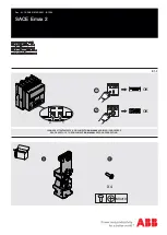
SACE Emax 2
Brand: ABB Pages: 7

61-627
Brand: IDEAL Pages: 54

4680001
Brand: PCE Health and Fitness Pages: 16


