ABB ADVAC 03, Installation & Maintenance Instructions Manual
The ABB ADVAC 03 is a high-quality electrical product designed for reliable performance. Ensure proper installation and maintenance by referring to the comprehensive "Installation & maintenance instructions manual". Download this manual for free from our website, giving you access to step-by-step guidelines and essential information to maximize the product's potential.
Share
Download


Reviews:
No comments
Related manuals for ADVAC 03

1652C
Brand: Fluke Pages: 66

The Hook
Brand: Power Probe Pages: 22

ETR4
Brand: Eaton Pages: 3

FRCdM-Type B
Brand: Eaton Pages: 2

T7-T7M-X1
Brand: ABB Pages: 12

SACE Tmax T6
Brand: ABB Pages: 5
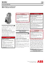
S800U
Brand: ABB Pages: 2
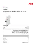
S201-K5
Brand: ABB Pages: 6

Record Plus FB100
Brand: ABB Pages: 4
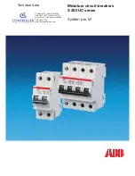
S 280 UC Series
Brand: ABB Pages: 16
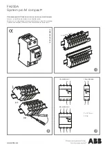
FH200A
Brand: ABB Pages: 2

F204 125 Series
Brand: ABB Pages: 2

Infinity NE-S
Brand: ABB Pages: 11

GE Power Break II GEH6271
Brand: ABB Pages: 10

Emax Series
Brand: ABB Pages: 10

K-Line Plus KDP-16
Brand: ABB Pages: 26

HPA 12kV
Brand: ABB Pages: 29

Mechanism HMB-8
Brand: ABB Pages: 34


