Weir MPM, Setup Manual
Introducing Weir MPM, an exceptional product accompanied by a comprehensive Setup Manual. This manual, available for free download from manualshive.com, offers detailed instructions to effortlessly set up and operate your Weir MPM. Enjoy hassle-free installation with our user-friendly manual, right at your fingertips!
Share
Download


Reviews:
No comments
Related manuals for MPM

GW-7472
Brand: B&B Electronics Pages: 60

460PSTCP-NNA4
Brand: RTA Pages: 93

L-Proxy
Brand: LOYTEC Pages: 150

EKI-1200-CE Series
Brand: Advantech Pages: 67

Echochange
Brand: Softing Pages: 4

IZAR IoT GATEWAY Compact
Brand: Diehl Pages: 4

LAN ECO Comfort
Brand: SiKom Pages: 2

NMEA 2000
Brand: Mercury Pages: 5

SURFboard SBG6400
Brand: ARRIS/Motorola Pages: 59

Touchstone TG862
Brand: Arris Pages: 2

Touchstone TG3452
Brand: Arris Pages: 2

OneStream GBRI
Brand: Telecom FM Pages: 8

SR516ac
Brand: SmartRG Pages: 158

Asycube
Brand: Asyril Pages: 41

1520
Brand: ActionTec Pages: 125
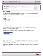
Archer VR1600v
Brand: TP-Link Pages: 5

SPCG310
Brand: Vanderbilt Pages: 5

HPD0440BNMR
Brand: HRW Pages: 43


