


English
Quick Installation Guide
Cassia X2000 Gateway
1 SAFETY INSTRUCTIONS
This simplified guide contains the necessary information for the correct installation, setup and use
of the Cassia X2000 gateway with the WEG Motor Scan sensor (smart monitoring device for motor
characteristics). The full manual and further information are available on
or through QR Code.
In this guide, the term "sensor" refers to the WEG Motor Scan device.
NOTE!
Follow the setup and installation recommendations described in Chapter 3 GATEWAY SETUP, Chapter
4 INSTALLATION and Chapter 5 SENSORS CONFIGURATION. Read the whole guide before installing,
setting or operating the gateway.
DANGER!
Only qualified people familiar with the gateway should plan or execute the installation, operation and
maintenance of this device. Such personnel must follow the safety instructions described in this guide
and/or defined by local regulations. Failure to comply with the safety instructions may lead to death
risk and/or damages to the gateway.
1.1 CONTENT AND STORAGE
At the receipt of the Cassia X2000 gateway, check that the packaging contains the following items:
1x Gateway X2000
2x Clamps
1x Silicone plug
1x PoE power
supply
2x Cable glands
4x Screws/
Bushings
1x Ethernet
cable
1x Bracket
1x Quick installation guide
Figure 1.1:
Gateway and its components
All damage complaints must be promptly submitted to the sender before installation.
NOTE!
It is recommended to store the gateway at a maximum temperature of 70
o
C and not exposed to
direct sunlight.
1.2 DISPOSAL AND RECYCLING
WEG is committed to the environment and supplies products that contribute to reduce the environmental impacts
along their life cycle. The user's participation in the waste sorting and recycling of electro-electronic devices is
also important to minimize their potential impact on the environment and human health. The proper disposal of the
gateway and its parts, observing the applicable laws, is very important for your safety and of the environment, in
addition to helping save resources.
ATTENTION!
For information on the return or collection for the proper disposal and recycling of the product, contact
WEG or send the gateway to one of our authorized service centers. The gateway should not be
disposed of with household, commercial or industrial waste. They cannot be disposed of in incinerators
and city landfills either. The gateway must be disposed of in compliance with the local regulations.
NOTE!
This symbol indicates that:
- At the end of its service life, the product must enter the recycling system.
- You should dispose of it separately at an appropriate collection point; do not dispose of it with
municipal solid waste.
- It is waste sorting of electric and electronic devices, and batteries.
- The horizontal bar below the garbage bin indicates the device was manufactured after August
13, 2005.
2 CERTIFICATIONS AND REGULATIONS
2.1 ANATEL APPROVAL
13481-21-12464
This device has no right to protection against harmful interference and cannot cause interference in duly
authorized systems.
2.2 FCC REGULATIONS (US)
It contains FCC ID: 2ALGLX2000
This equipment has been tested and found to comply with the limits for a Class B digital device, pursuant to part
15 of the FCC Rules. These limits are designed to provide reasonable protection against harmful interference
in a residential installation. This equipment generates, uses and can radiate radio frequency energy and, if not
installed and used in accordance with the instructions, may cause harmful interference to radio communications.
However, there is no guarantee that interference will not occur in a particular installation. If this equipment does
cause harmful interference to radio or television reception, which can be determined by turning the equipment
off and on, the user is encouraged to try to correct the interference by one or more of the following measures:
Reorient or relocate the receiving antenna.
Increase the separation between the equipment and receiver.
Connect the equipment into an outlet on a circuit different from that to which the receiver is connected.
Consult the dealer or an experienced radio/TV technician for help.
NOTE!
Any changes or modifications not expressly approved by the party responsible for compliance could
void the user's authority to operate the equipment. For additional information, please go to:
2.3 IC REGULATIONS (CANADA)
Eu Simplified Declaration of Conformity
This device complies with Industry Canada licence-exempt RSS standard(s). Operation is subject to the following
two conditions: (1) this device may not cause interference, and (2) this device must accept any interference,
including interference that may cause undesired operation of the device.
Le présent appareil est conforme aux CNR d'Industrie Canada applicables aux appareils radio exempts de licence.
l'Exploitation est autorisée aux deux conditions suivantes: (1) I'appareil ne doit pas produire de brouillage, et (2)
I'utilisateur de I'appareil doit accepter tout brouillage radioélectrique subi, même si le brouillage est susceptible
d'en compromettre le fonctionnement.
NOTE!
For additional information, please go to:
Cassia Networks, Inc.
Pour obtenir de l'Aide supplémentaire, rendez-vous sur:
Cassia Networks,
Inc.
2.4 RADIO EQUIPMENT DIRECTIVE (EU)
Eu Simplified Declaration of Conformity
Cassia Networks Inc., hereby declares that: Cassia X2000 Series Bluetooth Router is in compliance with
directives listed below:
EMC Directive 2014/30/EU
Low Voltage Directive 2014/35/EU
RED Directive 2014/53/EU
REACH European Regulation (EU) No 1907/2006
RoHS Directive 2011/65/EU & 2015/863/EU
WEEE Directive 2012/19/EU
The full text of the EU Declaration of Conformity is available at the following website:
.
DANGER!
RF exposure warning: This equipment must be installed and operated in accordance with provided
instructions and the antenna(s) used for this transmitter must be installed to provide a separation
distance of at least 20 cm from all persons and must not be co-located or operating in conjunction
with any other antenna or transmitter. End-users and installers must be provided with antenna
installation instructions and transmitter operating conditions for satisfying RF exposure compliance.
3 GATEWAY SETUP
NOTE!
The gateway is used to upload data from WEG Motor Scan sensors to the WEG Motion Fleet
Management
. The gateway must be configured to have Internet access
and registered with WEG Motion Fleet Management.
3.1 INITIAL GUIDELINES
For a better user experience, we recommend following the instruction sequence as presented in this guide. The
following points should be noted before beginning the gateway setup and installation.
1. The gateway cannot operate on virtual private networks (VPN).
2. The gateway cannot operate on proxy configured networks.
3. When using 3G/4G modems (dongles) on the gateway USB port, you should observe the presence of the selected
provider network signal. In low-signal locations, you may need an extension USB cable or an external antenna
for the modem.
4. WEG Motor Scan sensors in versions 2.0 or higher are enabled to communicate with the gateway only.
Before starting to set the X2000 Gateway, check that the firewall of the network to which it will be connected has
the ports and destinations of the tables below released.
Table 3.1:
List of ports to be released in the firewall
Protocol
Port
Direction
TCP
1883
Gateway -> Cloud
UDP
6246
Gateway -> Cloud
UDP
6247
Gateway -> Cloud
UDP
53
Gateway -> Cloud
TCP
433
Gateway -> Cloud
TCP
80
Gateway -> Cloud
TCP
9999
Gateway <-> Cloud
TCP
8001
Gateway <-> Cloud
TCP
8883
Gateway <-> Cloud
Table 3.2:
List of destinations to be released in the firewall
Destiny
IP
52.116.206.26
91.189.91.38
146.148.110.247
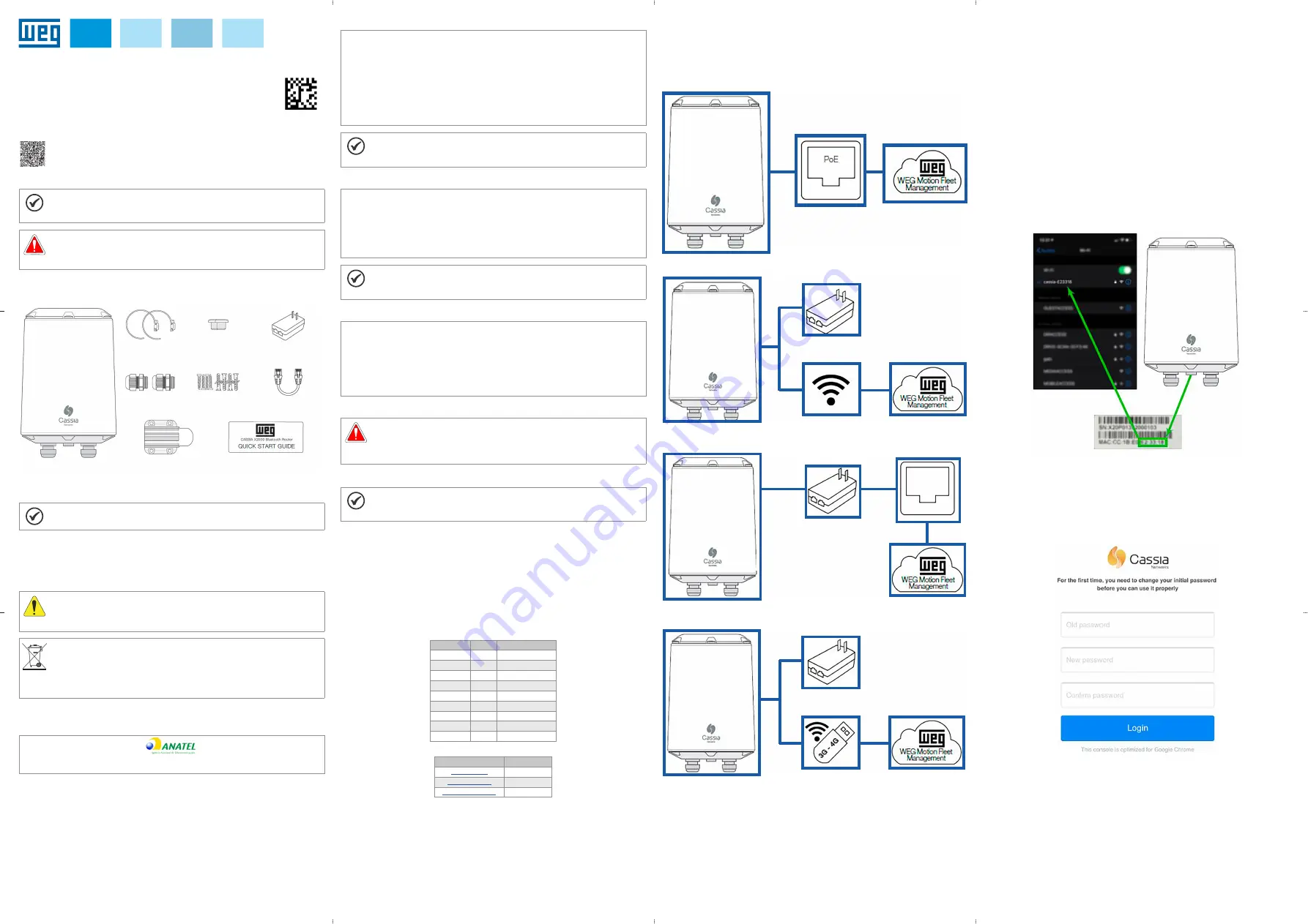
3.2 INTERNET CONNECTION
3.2.1 Infrastructure
The gateway requires an internet access port for setup and data upload from WEG Motor Scan sensors. It can be
connected to the Internet in four ways, as described below.
Power over Ethernet (PoE)
The network must have suitable infrastructure.
Gateway
Wi-Fi
Access Point (Wi-Fi)
Gateway
Power PoE
out
LAN/Ethernet
out
in
Gateway
LAN/Ethernet
Power PoE
Modem 3G/4G (dongle)
Gateway
out
Power PoE
Modem 3G/4G USB
3.3 GATEWAY REGISTRATION
The gateway must be added to WEG Motion Fleet Management
, at the plant of interest.
For this step, a smartphone containing the WEG Motor Scan app must be used. The steps to register the gateway
can be viewed directly in the app and in the full manual.
1. On the login screen, press "ENTER".
2. Enter your email address, password and press "ENTER" to access the WEG Motor Scan app home page.
3. App home page.
4. On the WEG Motor Scan app home screen, press "NEW DEVICE".
5. Press "SELECT" on the welcome screen.
6. Press "Cassia X2000" to start the procedure.
7. Make sure the gateway is turned on by checking the LED at the bottom base.
8. Select the plant in which the gateway will be registered.
9. Identify the gateway using its MAC address, located at its bottom base.
10. Connect to the gateway hotspot (iOS) or wait until the smartphone displays the nearby gateway network (Android).
11. Assign a name to your gateway to identify it in WEG Motion Fleet Management.
12. Make sure there is an internet connection and wait until the gateway is added to WEG Motion Fleet Management.
3.4 CONNECTION SETTINGS
3.4.1 Gateway Network Connection
1. Make sure the gateway is turned on checking the LED at the bottom.
2. Using a computer or smartphone, connect to the gateway Wi-Fi network.
3. The network address corresponds to the last 6 digits of the gateway MAC address. The network password is
the same as the address; for example, for the network cassia-A12345 the password will be cassia-A12345. The
following image illustrates where the gateway MAC address can be found.
4. If you cannot nd the gateway Wi-Fi hotspot, you must restart it by pressing and holding the reset button located
at the bottom of the gateway for 15 seconds.
Select Wi-Fi
Figure 3.1:
Location of the label with the MAC address used in the network SSID
3.4.2 Login
1. Use the web browser (preferably Google Chrome) to access the gateway page.
2. Enter the IP 192.168.40.1 in the address tab. The screen below illustrates the initial configuration portal.
3. Standard login
Username: admin
Old password: admin
New password: cassia-x2000
4. If the login data have been lost, it is possible to reset the gateway to factory default by pressing the reset button
at the bottom of the gateway for 15 seconds.
Figure 3.2:
Login screen
16271317
D
oc
ume
nt
: 1
0
0
09
03
54
84
/
0
0


