Watlow D4T, User Manual
The Watlow D4T user manual is available for free download on our website. This comprehensive manual provides detailed instructions and information on how to maximize the performance of your Watlow D4T product. Access the manual at manualshive.com and unlock the full potential of your device.
Share
Download


Reviews:
No comments
Related manuals for D4T
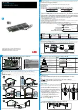
VSN300
Brand: ABB Pages: 2

VSN700
Brand: ABB Pages: 32

5005-0100
Brand: Dostmann Electronic Pages: 14

U1401A
Brand: Agilent Technologies Pages: 177

ProData 2
Brand: janitza Pages: 56

DL-200
Brand: Darfon Pages: 35

1486096
Brand: Eurochron Pages: 108

OM-USB-2404-UI
Brand: Omega Pages: 22

CL-200 Series
Brand: ICP DAS USA Pages: 221

nebolink
Brand: NEBO Pages: 4

ImagiProbe
Brand: Fourier Pages: 116

MultiLab
Brand: Fourier Pages: 149

DataNet
Brand: Fourier Pages: 212

PhaseLogE plus
Brand: Full Gauge Controls Pages: 4

Sitrad INBOX
Brand: Full Gauge Controls Pages: 22

CANedge1
Brand: CSS Pages: 66

LiveBase
Brand: AllSolus Pages: 2


