Wadkin LS, Operating And Instruction Manual
The "America Hears LS" user manual is your ultimate guide to getting started with this advanced listening device. Download this comprehensive manual for free from our website, ensuring that you have all the necessary instructions to unlock the full potential of your new device.
Share
Download


Reviews:
No comments
Related manuals for LS

03240
Brand: Toro Pages: 24

AOT-DC-80
Brand: Xiamen Pages: 4

SW12S
Brand: RASOR Pages: 15

Kongsberg XN IPC 2.0
Brand: Esko Pages: 165
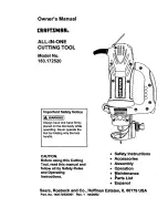
183.172520
Brand: Craftsman Pages: 26
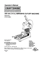
315.212900
Brand: Craftsman Pages: 26
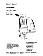
183.172510
Brand: Craftsman Pages: 23

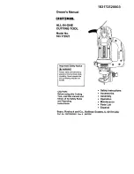
183.17253
Brand: Craftsman Pages: 18

183.172540
Brand: Craftsman Pages: 37

183.172500
Brand: Craftsman Pages: 47
183.172521
Brand: Craftsman Pages: 52

MS 4314
Brand: Okay Pages: 56

RCS3510
Brand: Land Pride Pages: 32

31847
Brand: Eastwood Pages: 12

Styro-Cut 3D
Brand: Cool Tool Pages: 21

P5200BC
Brand: P1PE Pages: 32

RAPTOR
Brand: Modern Pages: 99

H-1244
Brand: U-Line Pages: 6


