*941022-00*
941022-00
INSTALLATION INSTRUCTIONS
22 and 98/99 Rim and Vertical Rod Devices
(for 55 Rim Device, see other side)
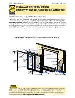
Figure 1
1.
Prepare inside face of door for exit device.
See exit device instructions for holes, line
X-X and center lines.
2.
Prepare outside face of door for cylinder.
A.
Transfer line X-X from exit device side of
door to cylinder side of door. Use extra
care if edge of door is beveled. Be sure
line X-X is parallel to edge of door.
B.
Locate and prepare all holes as shown.
3.
Apply cylinder.
A.
Cut cylinder tailpiece to proper length.
B.
Install cylinder and assemble component
parts (Figure 1).
4.
Apply cylinder mounting screw and tighten.
5.
Apply device.
A.
Remove key from cylinder.
B.
Attach lock stile case to door.
C.
Test key action.
LHR shown
RHR opposite
Standard rim cylinder
Cylinder base
Spacer collar
Cylinder disc
Cylinder screws
Cylinder thru bolt
For cutouts on inside face of door, see exit device instructions
22 and 98/99 Rim and Vertical Rod Devices (for 55 Rim Device, see other side)
X
X
1/4”
5/8”
1/4”
1/4” dia.
countersink
82° to 7/16” dia.
Corresponds to
center line of
exit device on
exit device
instructions
Wood Door
X
Line X-X corresponds to line X-X on exit device instructions
1-3/8” dia.
1-9/16”
7/16”
to
9/16”
1-3/8”
7/16”
to
9/16”
1/2”
dia.
Metal Door
Outside face
of lock stile
Inside face
of lock stile
C cylinder
L
C exit device
L
X
Cylinder Preparation
110NL
Installation Instructions