background image

Part Number: 631-0015-00

   December 2011

ViVOtech, Inc. 451 El Camino Real, Santa Clara, CA 95050 Ph: (408) 248-7001

Email: [email protected] URL: www.vivotech.com
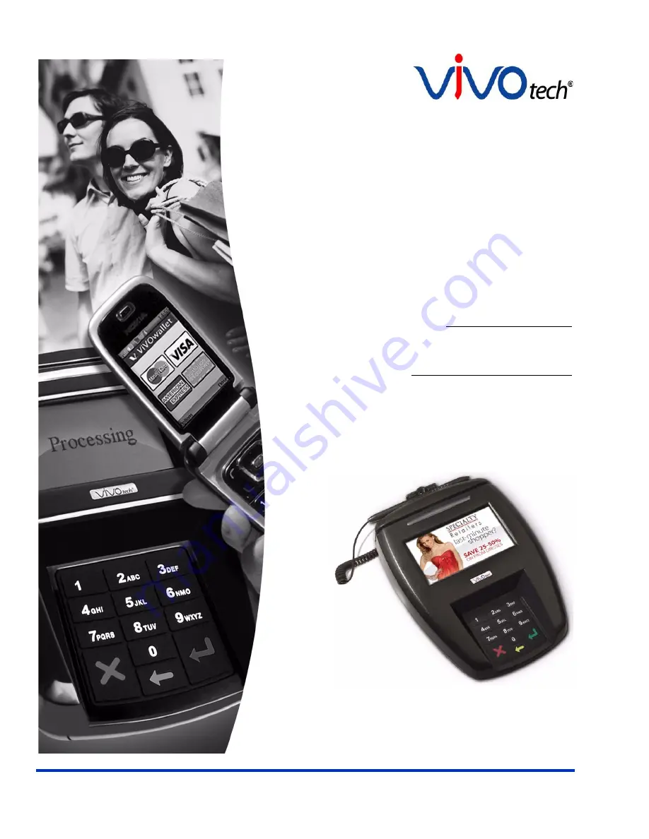
   

ViVOpay

®

8850 User Guide

Revision 1

Summary of Contents for 8850

Page 1: ...Part Number 631 0015 00 December 2011 ViVOtech Inc 451 El Camino Real Santa Clara CA 95050 Ph 408 248 7001 Email info vivotech com URL www vivotech com ViVOpay 8850 User Guide Revision 1 ...

Page 2: ...ectronic mechanical recorded or any other method or translated into another language or language form without the express written consent of ViVOtech Inc ViVOtech ViVOwallet ViVOnfc ViVOcard ViVOpay ViVOpersona and ViVOgiftcard are trademarks or registered trademarks of ViVOtech Inc Warranty Disclaimer The services and hardware are provided as is and as available and the use of these ser vices and...

Page 3: ...the Connectors 5 Connecting Power Stylus and Data Cables 6 Surface Mounting the ViVOpay 8850 10 Mounting the Wedge Bracket 11 Testing the Installation 12 Transaction Test 12 Chapter 3 Troubleshooting and Maintenance 13 Troubleshooting 13 Onboard Diagnostics 14 Accessing the OBD Tests 14 Test All 15 LCD Test 15 Touch Screen Test 16 Keypad Test 16 LED Test 16 Buzzer Test 17 Magstripe Test 17 RFID an...

Page 4: ...endix A Specifications 22 ViVOpay 8850 Specifications 22 Regulatory Compliance 22 FCC Part 15 Class A Equipment 22 FCC Information for User 23 Industry Canada Class A Equipment 23 Industry Canada Information for User 23 Glossary 24 ...

Page 5: ...ent applications MasterCard PayPass Magstripe v3 3 Visa payWave MSD v2 0 2 American Express ExpressPay v1 0 Discover Zip v1 0 Mifare ePurse Passthrough ViVOcard 1 2 and 3 This document assumes that users are familiar with their host POS systems and all related functions Features The following features are supported PCI 2 1 certified ISO14443 type A B and Mifare based contactless payment transactio...

Page 6: ...racket kit 540 0006 00 The ViVOtech data cables and power supply are specifically designed to meet FCC requirements If you are using other cables or power supply you must install ferrites available from ViVOtech For your free ferrite core kit with installation instructions please contact ViVOtech support ViVOpay 8850 P N 540 XXXX XX Stylus and cable P N 200 2515 00 Note The stylus may not be requi...

Page 7: ...omer to enter a PIN that can be viewed by a third party for example a customer must tilt or rotate the device for better accessibility due to objects blocking a card swipe 2 If the ViVOpay 8850 is elevated on a mounting stand shielding must be provided on the mount to prevent a PIN being viewed by a third party 3 If the ViVOpay 8850 is mounted on a counter top additional shielding which can includ...

Page 8: ...a to determine if there is a position where PIN entry can be observed Retesting Requirements If PIN entry on the ViVOpay 8850 is observable in any of the above tests you must reposition the ViVOpay 8850 and completely retest all locations to verify that PIN entry is not visible Consider placing a display to block observation from that position Repositioning the ViVOpay 8850 to block observance of ...

Page 9: ...ower and POS Mount if required Test the installation Connecting the ViVOpay 8850 Accessing the Connectors The ViVOpay 8850 connectors are beneath a cover on the bottom of the reader To access the connectors 1 Turn over the ViVOpay 8850 so that the connector cover is visible 2 Use a Phillips 1 screwdriver to release the captive screw holding the connector cover in place ...

Page 10: ...nvert the ViVOpay 8850 and try again Connecting Power Stylus and Data Cables There are connectors for data and power inside the connector cover There is also access to the SAM card slot if you are using this option To connect the ViVOpay 8850 1 Position the ViVOpay 8850 so that you can access the data stylus and power connectors Data port Power Stylus RS232 ...

Page 11: ...you are using an unpowered data cable insert the power supply cable into the power connector If you are using a powered data cable you do not need a separate power supply 3 Insert the data cable into the 10 pin RJ45 connector directly beside the power connector ...

Page 12: ... to the square 4 pin socket next to the data connector 5 Pass the cables through the slots in the connector cover Use the narrow slot for the power cable to provide strain relief 6 Replace the cover and secure it with the retaining screw 7 Turn the ViVOpay 8850 keypad side up ...

Page 13: ...screens before it displays the Welcome screen The opening screens include ViVOtech screen Copyright screen Firmware version screen It should then display Welcome or Please present card or similar wording depending upon the POS application If the unit fails to power up try reseating the power connector or change to a different power outlet If the unit still fails to power up try replacing the power...

Page 14: ... To mount the ViVOpay 8850 1 Drill four 3 5mm 9 64 inch holes in the surface where the ViVOpay 8600 will be mounted Use the hole spacing shown in Figure 1 Figure 1 Mounting hole locations 2 Position the ViVOpay 8850 over the mounting holes and use four M3 screws not supplied long enough to secure the ViVOpay 8850 to the mounting surface Mounting Holes x4 76 20 mm 3 0 inches 76 20 mm 3 0 inches ...

Page 15: ...other 11 for greater privacy The wedge bracket is fastened to the ViVOpay 8850 with the four mounting holes To mount the wedge bracket 1 Align the mounting bracket over the mounting holes with the thickest end over the connector cover 2 Fasten in place with four M3 screws as shown in Figure 2 Figure 2 Attaching the wedge bracket ...

Page 16: ...To test a transaction 1 Ring up a transaction on the POS The ViVOpay 8850 may show Welcome or similar wording 2 Present a card fob phone in close proximity to the reader or swipe a magnetic stripe card 3 A single beep and LED flash indicates that the card has been validated The ViVOpay 8850 may display Processing or similar wording while the transaction is being processed 4 If the POS software req...

Page 17: ...ered on or incorrect voltage Incorrect power supply used Unsupported card fob phone used Present card fob phone closer to the reader and ensure it s parallel to the reader touch screen Verify that the card fob phone is valid current Test with ViVOcard Contactless Test Card part number 241 0015 03 Try a different card fob phone Verify that the unit is not near any large metal objects Verify that co...

Page 18: ...rameters Check that the cable connection is secure and in the correct port on the POS ECR Check that the POS ECR has the correct software application to accept data from the contactless reader may need assistance from the POS vendor Try a different card fob phone or magstripe card if testing the magstripe reader If testing with the magstripe card try turning the card around make sure that the card...

Page 19: ...d 2 Press 1 All pixels should be turned on and the screen should be a gray color 3 Press Enter if the correct screen is displayed otherwise press X to fail the test The AR LCD Test screen is displayed 4 Press 2 All pixels should be turned off and the screen should be bright 5 Press Enter if the correct screen is displayed otherwise press X to fail the test The AR LCD Test screen is displayed 6 Pre...

Page 20: ...hed the main menu screen appears Keypad Test This test asks you to enter each of the keys in sequence to verify that the keypad is working correctly The results will be displayed on the LCD 1 Press 4 on the ViVOpay AR Diagnostics screen The Keypad Test screen is displayed 2 Press key 1 The screen then asks for the next key in sequence 3 Continue pressing each key as requested 4 Press the X key whe...

Page 21: ...uzzer Test screen is displayed 2 Listen for the tones and make sure they ramp up and then down 3 Press Enter if you hear the tones otherwise press X to indicate that the tones did not ramp up and down Magstripe Test This test asks you to swipe a magstripe card through the slot at the top of the ViVOpay 8850 and displays the tracks read correctly The results will be displayed on the LCD 1 Press 7 o...

Page 22: ...uccessfully read or an error is indicated 3 Press any key to return to the ViVOpay AR Diagnostics screen RFID and Antenna Test This test asks you to present a contactless card phone fob close to the touch screen to verify that the antenna is able to detect a contactless card The results will be displayed on the LCD 1 Press 8 on the ViVOpay AR Diagnostics screen The RFID Test screen is displayed RF...

Page 23: ...verifies which slot contains the master Key The results will be displayed on the LCD 1 Press 9 on the ViVOpay AR Diagnostics screen The Security Elements Test screen is displayed 2 Press any key to return to the ViVOpay AR Diagnostics main menu Test Results Summary The the Test All option was selected the Test Results Summary displays the results of all tests performed Once the ViVOpay 8850 is ret...

Page 24: ...ace the stylus 1 Turn the ViVOpay 8850 upside down and unscrew the connector cover retaining screw You must place upward tension on the screw to remove it completely from the connector cover 2 Remove the old stylus if needed The connector has a locking tab you must squeeze to remove the stylus connector 3 Connect the new stylus to the ViVOpay 8850 4 Replace the cover as described in Connecting Pow...

Page 25: ...are using for the upgrade 3 Copy the vivopay inf file to the Windows inf directory 4 Connect the USB data cable to the ViVOpay 8850 and PC see Connecting Power Stylus and Data Cables on page 6 5 Double click the ViVOpay download utility icon or exe to start the utility 6 Power on the ViVOpay 8850 The bootloader version appears under the ViVOtech logo 7 Click Download Image 8 When prompted locate a...

Page 26: ...r installation If this equipment does cause harmful interference to radio or television reception which can be determined by turning the equipment off and on the user is encouraged to try to correct the interference by one or more of the following measures Reorient or relocate the receiving antenna Increase the separation between the equipment and receiver Connect the equipment into an outlet on a...

Page 27: ... information in that form Industry Canada Class A Equipment This Class A digital apparatus complies with Canadian ICES 003 Cet appareil numérique de la classe B est conforme à la norme NMB 003 du Canada Industry Canada Information for User Operation is subject to the following two conditions 1 This device may not cause harmful interference and 2 this device must accept any interference including i...

Page 28: ...ne Near Field Communications NFC phone A technology that enables communication between a secure element in a mobile device and a contactless reader to make credit debit payments Also see UICC PCI 2 1 The Payment Card Industry Security Standards Council PCI SSC mission is to enhance payment account data security PCI 2 1 is a set of standards created by PCI SSC to increase the security of card data ...

Reviews: