background image

All users should read the user manuals for complete details on installation, usage and functionality.

Quick Installation Guide

1

Nextiva S5100 - FD Models

Hardware Overview

The S5120FD features a 2-Megapixel sensor.


Setting the Video Standard

The Nextiva S5100 series IP cameras can run in one of two video standards (NTSC or PAL).

Perform the following:

1. On the back of the device move the DIP switch to NTSC or PAL.

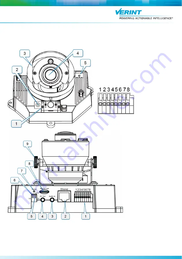
Front View Description:

1. Status LED
2. Built-in microphone
3. Lens hood
4. Lens
5. Auto Focus button

Terminal Block 

Description:

1. Ground
2. 12V DC input
3. 24V AC input
4. 24V AC input
5. Ground
6. Dry contact input
7. Relay output
8. 12V DC output

Rear View Description:

1. Terminal Block
2. RJ-45 ethernet connector
3. Audio In
4. Audio/Video Out
5. NTSC/PAL switch
6. Microphone internal/external switch
7. Hardware reset button
8. Micro SD/SDHC Card slot
9. Tilt Adjustment Screw

Summary of Contents for Nextiva S5120FD

Page 1: ... following 1 On the back of the device move the DIP switch to NTSC or PAL Front View Description 1 Status LED 2 Built in microphone 3 Lens hood 4 Lens 5 Auto Focus button Terminal Block Description 1 Ground 2 12V DC input 3 24V AC input 4 24V AC input 5 Ground 6 Dry contact input 7 Relay output 8 12V DC output Rear View Description 1 Terminal Block 2 RJ 45 ethernet connector 3 Audio In 4 Audio Vid...

Page 2: ...icker to the wall 3 Drill three pilot holes through the three circles on the sticker into the wall 4 Hammer the supplied plastic anchors into the holes 5 Insert the supplied three screws on each side of the camera base 6 Secure the camera to the ceiling with a screwdriver To install on the wall 1 Remove the dome cover using the supplied screwdriver 2 Attach the supplied alignment sticker to the wa...

Page 3: ...on the side of the IP camera 2 Plug the other end of the cable into a POE ethernet switch or to the DATA PWR port of a POE injector To use a 12V DC power supply 1 Connect the DC power supply cable to pin 1 GND and 2 on the terminal block 2 Plug a category 5e cable into the RJ 45 connector on the side of the IP camera 3 Plug the power supply cable to the power outlet To use a 24V AC power supply 1 ...

Page 4: ...djust the focus range 1 Connect the 1 8in 3 5mm jack from the Video to BNC connector to the Audio Video out connector 2 Connect the BNC connector to a CCTV test monitor 3 Press the auto focus button Press the button for less than two seconds to initiate a short cycle auto focus This corrects a view that is slightly out of focus Press the button for more than two seconds to initiate a long cycle au...

Page 5: ... obtains a valid IP configuration If the DHCP configuration fails the IP camera assigns itself a temporary IP address based on the Automatic Private IP Addressing APIPA format To configure SConfigurator 1 On a computer download the latest version of SConfigurator from www verint com manuals 2 Extract the executable file SConfigurator exe to the desktop 3 Double click SConfigurator exe to start SCo...

Page 6: ...the IP camera 7 In the Subnet Mask box type the subnet address in which the IP address belongs 8 In the Gateway box type the IP address of the server that acts as an access point to another network NOTE No gateway is required to communicates with other devices on the same subnet 9 In the Host Name box type a unique name for the IP camera 10 Click OK to close the dialog box 11 Click Exit to close S...

Reviews: