US Conec MTP Series, Loopback Casing Installation
The RICE HYDRO MTP Series is a versatile and high-quality product designed for various assembly and operating tasks. Ensure a seamless experience by downloading the free assembly and operating instructions manual from our website. Get the most out of your product with step-by-step guidance and accurate information.
Share
Download


Reviews:
No comments
Related manuals for MTP Series

CABLINE-UM PLUG
Brand: I-PEX Pages: 20

RJ45CFXL-P1
Brand: Sommer Cable Pages: 2

A060-006
Brand: Tripp Lite Pages: 2

SeaLINK+422
Brand: SeaLevel Pages: 34

EXT-HDMI1.3-145
Brand: Gefen Pages: 26

EYP A A00Q01 Series
Brand: Lenze Pages: 6

powerCON
Brand: NEUTRIK Pages: 2

SV 9677.910
Brand: Rittal Pages: 12

43099
Brand: Lindy Pages: 2

Roto-Twist RT-150
Brand: MAT Pages: 2

RTX-30
Brand: Atlas Copco Pages: 2

7849211-30
Brand: MAC Panel Pages: 4

EX-G048D
Brand: Ace Plus Pages: 8

C2N-TXM-C50
Brand: Crestron Pages: 2
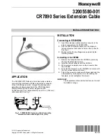
CR7890 Series
Brand: Honeywell Pages: 2

SIRIUS 3RT261.-1 Series
Brand: Siemens Pages: 9

TA4NG500
Brand: Siemens Pages: 4

SIRIUS 3RK1901-1MX02
Brand: Siemens Pages: 4


