


Personal Safety Equipment
Use - Safety Glasses
Yes
Use - Safety Gloves
Use - Safety Boots
Use - Breathing Masks
Yes
Use - Ear Protectors
Read these instructions carefully before installing, operating,
servicing or repairing this tool. Keep these instructions in a safe
accessible place.
Important
Includes - Foreseen Use, Work Stations, Putting Into Service, Operating,
Dismantling, Assembly and Safety Rules
Operator Instructions
Manufacturer/Supplier
Product Type
RPM
Cycles Per Min
Model No/Nos
Serial No (if any)
Product Nett Weight
lbs
Kg
Recommended Use Of
Balancer Or Support
Recommended Hose Bore
Size - Minimum
Recommended Max.
Hose Length
Ins
M/M
Ft
M
No
Page No 1
20mm Belt Sander
UT5765
2.53
1.15
3/8
10
30
10
16,000
Universal Air Tool Company Limited
Unit 8
Lane End Industrial Park
High Wycombe
Bucks
HP14 3BY
Work Stations
The tool should only be used as a hand held hand operated tool. It is
always recommended that the tool is used when standing on a solid
floor. It can be used in other positions but before any such use the
operator must be in a secure position having a firm grip and footing
and be aware of the safety rules to be obeyed when using the sander.
Foreseen Use of the Tool
The tool is designed for the purpose of cleaning or sanding of
materials using a continuous abrasive belt. Belts are available in
various grades to suit fine finishing or fast material removal.
Do not use the tool for any other purpose than that for which it was
designed. Do not modify this tool for any other use or for its use as a
belt sander without first consulting the manufacturer or the
manufacturer’s authorised distributor.
Putting Into Service
Air Supply
Use a clean lubricated air supply
that will give a measured air
pressure at the tool of 90 p.s.i./6.3
bar when the tool is running with
the trigger/lever fully depressed.
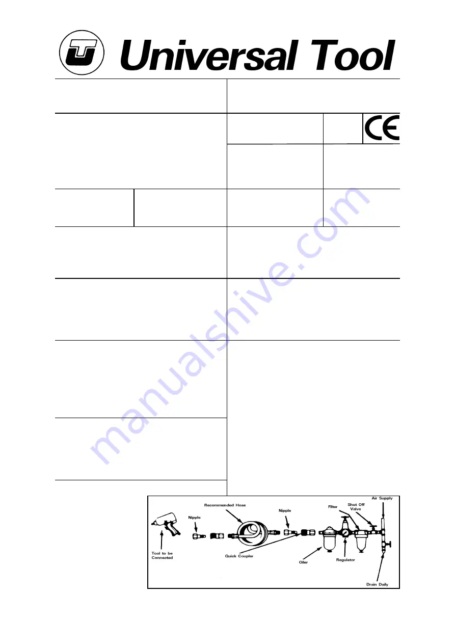
Use recommended hose size and
length. It is recommended that the
tool is connected to the air supply
as shown in figure 1. Do not
connect the tool to the air line
Tel No
Fax No
(01494) 883300
(01494) 883237
system without incorporating an easy to reach and operate air shut off
valve. The air supply should be lubricated. It is strongly recommended
that an air filter, regulator, lubricator (FRL) is used as shown in Figure
1 as this will supply clean, lubricated air at the correct pressure to the
tool. Details of such equipment can be obtained from your supplier. If
such equipment is not used then the tool should be lubricated by
shutting off the air supply to the tool, depressurising the line by
pressing the trigger on the tool. Disconnect the air line and pour into
the intake bushing a teaspoonful (5ml) of a suitable pneumatic motor
lubricating oil preferably incorporating a rust inhibitor. Reconnect tool
to air supply and run tool slowly for a few seconds to allow air to
circulate the oil. If tool is used frequently lubricate on daily basis and if
tool starts to slow or lose power.
It is recommended that the air pressure at the tool whilst the tool is
running is 90 p.s.i./6.3 bar. The tool can run at lower and higher
pressures with the maximum permitted working air pressure of 100
p.s.i./7 bar.
Noise Level
Sound Pressure Level 84.7 dB(A)
Test Method
Tested in accordance with Pneurop
test code PN8NTC1 and ISO Standard 3744
Sound Power Level 95.8 dB(A)
Vibration Level
Test Method
Tested in accordance with ISO
standard 8662/1
Less than 2.5
Metres / Sec²
Air Pressure
Recommended Working
6.3
bar
90
PSI
Recommended Minimum
n/a
bar
n/a
PSI
Maximum
7
bar
100
PSI


