background image

No.27700-2-01-8


INSTRUCTION MANUAL 

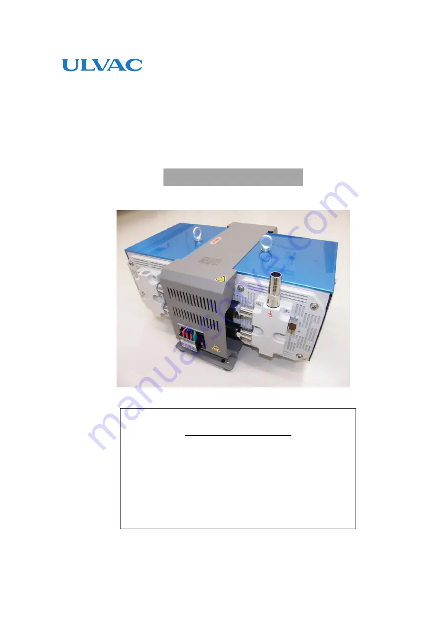
Diaphragm-type Dry Vacuum Pump 

Model: DAL-181D, 361S 


Request to Users 

Please read this manual thoroughly to ensure safe and 
effective use of the equipment. 
Keep this manual in a safe place. 
Due to periodic improvements in performance, the 
equipment described in this manual is subject to 
changes in dimensions and specifications without prior 
notice. 


ULVAC KIKO,Inc. 


Summary of Contents for DAL-181D

Page 1: ...Users Please read this manual thoroughly to ensure safe and effective use of the equipment Keep this manual in a safe place Due to periodic improvements in performance the equipment described in this...

Page 2: ...Fitting Piping 3 7 Piping 3 8 Storage 4 Cautions for Operation 4 1 Cautions for Operation 4 2 Operation of the Thermal Protection Relay 4 3 Precautions when starting 5 Pump Performance 5 1 Pressure Ac...

Page 3: ...gion of the voltage and frequency Fig 3 2 Wiring Diagram Fig 3 3 Fitting Piping Fig 3 4 Example of Piping Used When Evacuating a Vessel Table 1 1 Product Specifications Table 6 1 Consumables List Tabl...

Page 4: ...uipment correctly Read the section on Safe Use particularly closely Keep This Manual in a Safe Place After reading this manual be sure to keep it in a safe place which is readily accessible to others...

Page 5: ...1 Note Piping is not fitted Fit after opening the package see 3 6 Fitting Piping on P5 3 Is the pump damaged in any way 4 Are any external screws or inlet and outlet pipes loose Are any components mi...

Page 6: ...be followed Safety icons The meanings of the safety icons are as follows Incorrect handling of the equipment is very likely to result in death or serious injury to the operator Incorrect handling of t...

Page 7: ...e the power cord from the wall socket before checking or repairing the pump Failure to do so may result in electric shock or the pump suddenly starting and causing injury 5 Ensure that the relevant wi...

Page 8: ...ed by the manufacturer 18 To prevent ingestion of microscopic particles resulting from wear of components use a dust mask and gloves when replacing diaphragms valves and O rings Installation 1 To prev...

Page 9: ...ately after having been switched off may result in burns 7 Do not insert fingers or objects into or peer into the inlet or outlet during operation Maintenance and Repair 8 If the pump ceases operation...

Page 10: ...ng appropriate caution during maintenance 5 Entry of corrosive gases organic solvents fluids or gases able to be condensed eg steam may result in damage to the pump and prevent normal operation 6 Entr...

Page 11: ...r long periods at near atmospheric pressure 1 2 Specifications Table 1 1 Product Specifications Model DAL 181D DAL 361S Voltage 200 Exhaust rate 50Hz 180 L min 360 L min 60Hz 210 L min 390 L min Opera...

Page 12: ...View Fig 2 1 DAL 181D and 361S Dimensions 3 Installation and Storage 3 1 Cautions for Installation and Storage See Warning 1 2 3 5 6 7 8 9 10 11 12 13 P04 See Caution 1 2 3 P05 See Note 1 P07 Warning...

Page 13: ...on and cleaning Particular attention should be paid to ambient temperature when fitting the pump to equipment Use anti vibration rubbers to isolate the pump from vibrations in the equipment See 3 2 En...

Page 14: ...power cable to the pump terminal block install the switch between the terminal block and the power supply and insert the power cable plug into regulation voltage socket see Fig 3 2 Wiring Diagram Not...

Page 15: ...se of selecting the inlet pipe and outlet pipe that are not from our products please select the outlet pipe that has same or larger inner diameter length with the inlet pipe 5 When evacuating a vessel...

Page 16: ...onditions and the pump may be difficult to start Use the following procedure in this case 1 Open the inlet to atmosphere and switch power ON OFF two or three times until the pump starts If the pump st...

Page 17: ...introduce other gases resulting in increased pressure 5 2 Evacuation Rate The rate of evacuation for the pump varies with the type of gas entering the inlet and its pressure The maximum rate of evacua...

Page 18: ...e pump 3 Check that gas is discharged normally If a problem is found take the measures described in 6 5 Troubleshooting List 6 3 Regular Inspections After commencement of use inspect consumables after...

Page 19: ...ng symptoms become apparent Inlet filters Clean if filter is dirty or has rubbish on it Exhaust filters Replace if filter is dirty clogged or hard Diaphragms Replace if worn hard or deformed or if sur...

Page 20: ...ure Always put on dust mask and gloves before replacing diaphragms and valves Any fine particles produced by mechanical wearing may become airborne causing a health risk if inhaled Prepare the followi...

Page 21: ...eyebolt M8 flat washer M10 truss head screws M5 10 and remove the pump panels 1 and 2 Photo 1 2 2 The piping black is visible when the panels are removed Remove the pump head as described below and t...

Page 22: ...agm in a clockwise direction until it stops Tighten a further 5 10 from that position Photo 5 Note Take care not to over tighten 2 3 Fitting Pump Heads 1 Place the pump head on the casing so that the...

Page 23: ...ump head and diaphragm occurs it will make a noise and cause the pump head to vibrate Switch off the machine and contact the manufacturer s service division 7 Temporarily fix the pump panel 1 in place...

Page 24: ...lbow T joint T joint Photo 17 Fan side Photo 16 Terminal Block side Straight piping T joint T joint Straight piping Photo 12 Terminal Block side Photo 13 Fan side Photo 14 Piping Photo 15 Top View T j...

Page 25: ...d the area on the pump head where the valve was fastened 5 Fasten one valve A marking downwards to the inlet slot of side 1 and side 2 and then fasten one valve A marking upwards and one valve clamp A...

Page 26: ...Tighten diagonally opposite pairs of hexagonal bolts to 6N m with the torque wrench a number of times Note When viewed from side on the O ring should be hidden from view 8 Fix the pump head in place...

Page 27: ...d fix it in place with the hexagonal bolts M5 16 Photo 24 Note Fasten so that the inlet side of the valve retainer connects to the inlet side slot of the pump head Note Tighten diagonally opposite pai...

Page 28: ...any vacuum grease on the fastener parts Fix the long hose nipples L 1 L 2 S and the G 1 2 plug with a spanner Note Do not over tighten Over tightening can damage the O rings 5 Remove the Pump Head s O...

Page 29: ...ng T joints elbows straight pipes synflex tubes and connecting tubes with new parts Note When replacing piping lightly apply vacuum grease to the connecting areas of the piping and then connect the pi...

Page 30: ...to be Replaced Top View Piping for DAL 360S Unit with pump heads and piping fitted T joint L shaped hose connection Elbow Connecting tube Connecting tube Fan side Terminal Block side Elbow T joint T j...

Page 31: ...3 Use solvent to clean the fastening area of the exhaust filter Photo 27 4 Fit the new exhaust filter taking care to prevent it from collapsing in Then check to make sure the exhaust filter is not de...

Page 32: ...her pump 2 Pressure measurement is incorrect 2 Measure the pressure correctly 5 1 3 Vacuum gauge is unsuitable 3 Measure with a calibrated vacuum gauge suitable for the pressure range 5 1 4 The inlet...

Page 33: ...and inspection etc d Malfunctions caused by modifications or repairs carried out by a party other than the manufacturer or by a service company not approved by the manufacturer e Malfunctions caused...

Page 34: ...Industrial Safety and Health Law designates particular substances as the materials to be notified 2 Usage Status Operation Method Approx hours per day years and months Continuous Operation Intermitte...

Page 35: ...6 6397 2286 ULVAC KIKO Inc https ulvac kiko com en Please contact us for products Service Base or other Inquiries from here ULVAC Inc Components Division 2500 Hagisono Chigasaki Kanagawa 253 8543 Japa...

Reviews: