


Reviews:
No comments
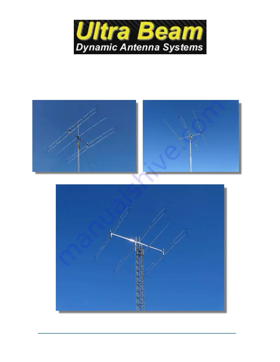
Related manuals for UB640-VL2.3

LP-349
Brand: Lanpro Pages: 7

GPS 17x NMEA 0183 HVS
Brand: Garmin Pages: 48

AM-M-V5G-Ti
Brand: Ubiquiti Pages: 20
1500254
Brand: Radio Shack Pages: 8

303CP26
Brand: M2 Antenna Systems Pages: 5

AP-5AC-90-HD Air Prism
Brand: Ubiquiti Pages: 12

VQ4200
Brand: King Quest Pages: 36

27801RG
Brand: SLX Pages: 2

RetroAntenna PA01
Brand: RetroSound Pages: 4

CRUISER
Brand: Scout Pages: 8

PST
Brand: PRO.SIS.TEL. Pages: 21

ORITEL SAN 100
Brand: Chauvin Arnoux Pages: 4

ORITEL ANF 100
Brand: Chauvin Arnoux Pages: 4

active monopole series
Brand: A.H. Systems Pages: 13

LS 86
Brand: Acom Pages: 15

LABGT12K
Brand: Labgear Pages: 2

TD Series
Brand: TENNADYNE Pages: 6

MBL001
Brand: Oricom Pages: 2


