U-Line UMCR015-SS01A, User Manual & Service Manual
The U-Line UMCR015-SS01A is a top-of-the-line product designed for efficiency and convenience. This compact refrigerator offers outstanding performance and the user manual and service manual are available for free download from our website. Get ready to enjoy its impressive features and functionalities with the help of these comprehensive manuals.
Share
Download


Reviews:
No comments
Related manuals for UMCR015-SS01A

CM200
Brand: Barista Mate Pages: 14
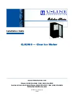
CLR2160
Brand: U-Line Pages: 20

delish DDWB9OO
Brand: Dash Pages: 17

CK630
Brand: Buffalo Pages: 56

PLUS 10 COF
Brand: La San Marco Pages: 36

CM-103720
Brand: Waves Pages: 19

COFFE BOX
Brand: OBH Nordica Pages: 28

00111274
Brand: Xavax Pages: 40

PRO YM350 Series
Brand: Waring Pages: 20

Prodigio & Milk
Brand: Nespresso Pages: 76

029112
Brand: Lagrange Pages: 62

ULN-SS98NF-03A
Brand: U-Line Pages: 50

GLEC02S3CT14
Brand: Galanz Pages: 7

Disney 645
Brand: ARIETE Pages: 5

AquaCafe
Brand: MTN Products Pages: 3
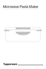
10049020724
Brand: Tupperware Pages: 47

the Barist Express SES875
Brand: Sage Pages: 48

PRO Plus 40T
Brand: Bartscher Pages: 93


