TSC PEX-1120 Series, Service Manual
The TSC PEX-1120 Series product offers high-performance printing capabilities for various applications. With its user-friendly design, users can easily navigate the functionalities using the comprehensive Service Manual available for free download at manualshive.com. Explore the full potential of this product and enhance your printing experience with the detailed manual.
Share
Download


Reviews:
No comments
Related manuals for PEX-1120 Series

PRO ES1500 Vero Barista
Brand: Waring Pages: 2

643-111
Brand: Melissa Pages: 1

PID
Brand: Ascaso Pages: 6

SCE 3000BK
Brand: Sencor Pages: 10

SZ-7510-C
Brand: Sub-Zero Pages: 5

740816308
Brand: Saeco Pages: 100

IMPRESSA X9
Brand: Jura Pages: 4

BM8010
Brand: TREVIDEA Pages: 64
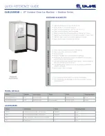
CLR1215SOD
Brand: U-Line Pages: 2

NORDIC B230-AP
Brand: Cornelius Pages: 2

All-in-one
Brand: EspressoWorks Pages: 8

ES-2010
Brand: Optimum Pages: 51

Onyx 28016
Brand: Unold Pages: 44

SBR 0770WH
Brand: Sencor Pages: 12

Spectra 107/12
Brand: Carl Valentin Pages: 172
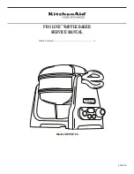
Pro Line KPWB100
Brand: KitchenAid Pages: 12

Pro Line KPWB100
Brand: KitchenAid Pages: 88

6130
Brand: West Bend Pages: 24


