


1
5
8
3
6
10
2
9
4
7
11
12
13
1
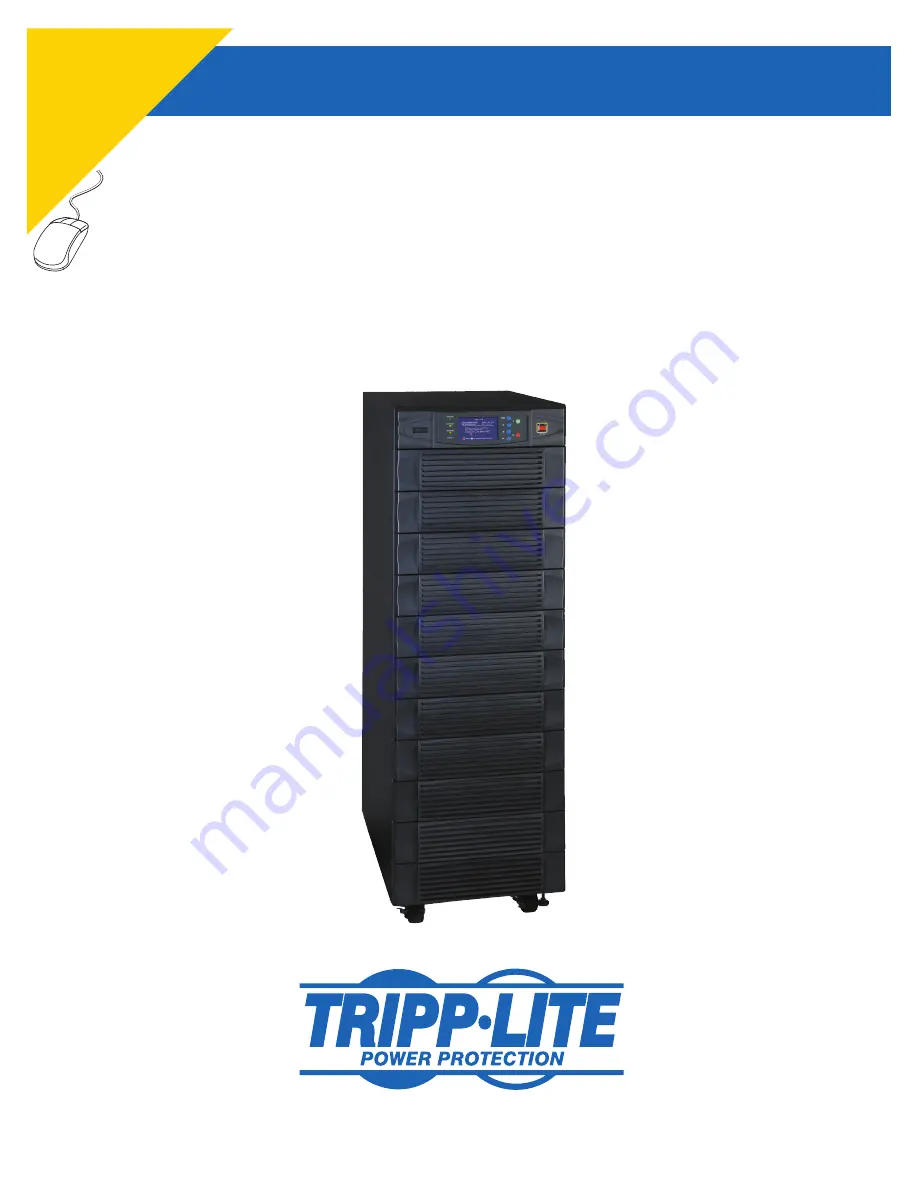
SmartOnline
™
3-Phase UPS System
Model: SU80K
Input/Output: 120/208V AC, 50/60 Hz, 3Ø, 4-wire + ground
Not suitable for mobile applications.
1111 W. 35th Street, Chicago, IL 60609 USA
www.tripplite.com/support
Copyright © 2010 Tripp Lite. All trademarks are the sole property of their respective owners.
Owner’s Manual
PR
OT
EC
T Y
OU
R
INVESTMENT!
Co
m
ple
ted
an
d s
ign
ed
st
ar
t-u
p f
or
m
s
M
US
T
be
su
bm
itte
d a
nd
ap
pr
ov
ed
by
Tripp Lite to activ
ate y
our w
arr
anty
.


